S1
S2
HeX
DeC
0
0
0
1
16
1
2
32
2
3
48
3
4
64
4
5
80
5
6
96
6
7
112
7
8
Not
Used
for
CAN
Addr
8
9
9
A
10
b
11
C
12
D
13
e
14
f
15
S2
S1
X1
X10
DEVICE ID
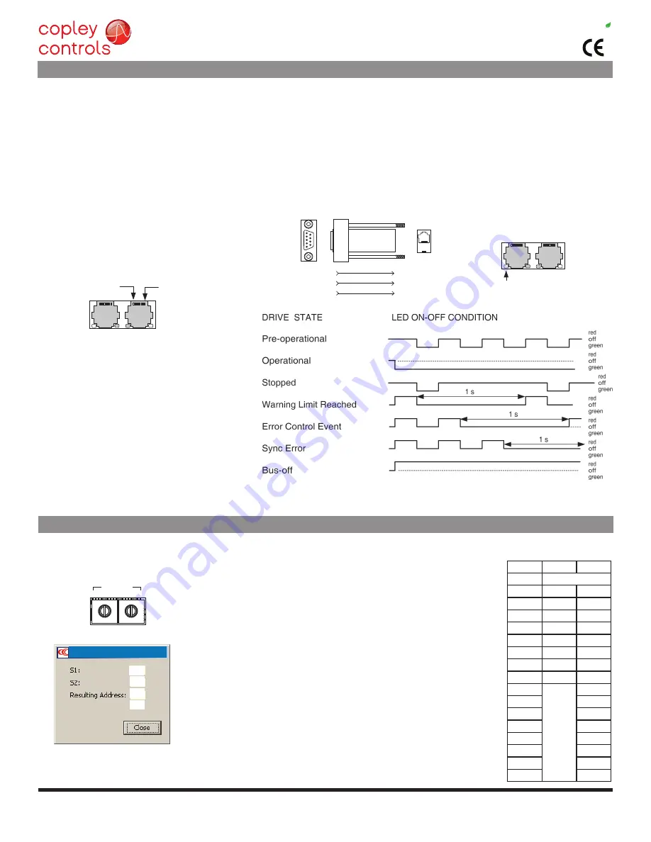
CAN Status LED
J7
6
9
1
5
D-Sub 9F
3
3
2
2
1
8
CAN_L
CAN_GND
CAN_H
CAN_L
RJ-45
CAN_GND
CAN_H
7
1
J7
Pin 8
Pin 1
Copley Controls, 20 Dan Road, Canton, MA 02021, USA
P/N 16-01436 Rev 01
Page 5 of 28
RoHS
Xenus
PLUS
Compact
CANopen
XPC
can network node-Id (address)
canopen coMMunIcatIons
Xenus uses the Can physical layer signals Can_H, Can_l, and Can_Gnd for connection, and Canopen protocol for communication.
before installing the drive in a Can system, it must be assigned a Can address. a maximum of 127 Can nodes are allowed on a single
Can bus. The rotary switch on the front panel controls the four lower bits of the seven-bit Can address. When the number of nodes on
a bus is less than sixteen, the Can address can be set using only the switch. address 0 is reserved for the Can bus master.
for installations with sixteen or more Can nodes on a network Cme 2 can be used to configure Xenus to use the rotary switch,
or combinations of digital inputs and programmed offset in flash memory to configure the drive with a higher Can node address.
for more information on Canopen communications, download the Canopen manual from the Copley web-site:
http://www.copleycontrols.com/motion/downloads/pdf/CanopenProgrammersmanual.pdf
note: red & green led on-times do not overlap.
led color may be red, green, off, or flashing of either color.
CAN StAtUS leD
CANoPeN CoNNeCtoRS
dual rJ-45 connectors that accept standard ethernet
cables are provided for Can bus connectivity. Pins
are wired-through so that drives can be daisy-
chained and controlled with a single connection
to the user’s Can interface. a Can terminator
should be placed in the last drive in the chain.
The XP2-nk connector kit provides a d-Sub adapter
that plugs into a Can controller and has an rJ-45
socket that accepts the ethernet cable.
XP2-nk Can ConneCTor kIT
The kit contains the XP2-CV adapter that converts the Can interface d-Sub
9m connector to an rJ-45 ethernet cable socket, plus a 10 ft (3 m) cable and
terminator. both connector pin-outs conform to the Cia dr-303-1 specification.
J7 Can ConneCTIonS
Note: Red & green led on-times do not
overlap. LED color may be red, green, off,
or flashing of either color.
neT (Can STaTuS) led
a bi-color led gives the state of the Can connection
in accordance with the Can-Cia specification 303,
part 3.
The green (run) led shows the state of the
Canopen state machine. The red (err) led shows
the occurrence of errors (sync, guard, or heartbeat)
and of the Can bus physical layer.
during a reset condition, the green led will be off.
In operation, the red & green colors will alternate
with the number of blinks or on/off condition shown
in the table to the right.
In an Canopen network, nodes are assigned addresses 1~127. address 0 is reserved for the Can bus
master. In the XPC, the node address is provided by two 16-position rotary switches with hexadecimal
encoding. These can set the address of the drive from 0x01~0x7f (1~127 decimal). The chart shows the
decimal values of the hex settings of each switch.
node-Id (address) Switches
Cme2 -> amplifier -> network Configuration
To find the node-Id given the switch settings:
node-Id = (S1 * 16) + S2
example: S1 = 5, S2 = b
S1 value = (5*16) = 80, S2 value = Hex(b) = 11,
node-Id = 80 + 11 = 91
To find the switch settings for a given address:
S1 = The integer part of (node-Id / 16)
S2 = Hex (node-Id - (S1 * 16) )
example: node-Id = 91
S1 = 91/16 = 5.69, integer part = 5, (5*16) = 80
S2 = Hex (91 - 80) = 11 = 0xb
b
5
5b
91
Canopen Settings


