Signal
J5 Pins
Clk
9
/Clk
8
Data
15
/Data
14
Sin(+)
19
Sin(-)
18
Cos(+)
21
Cos(-)
20
+5V
6, 17
Sgnd
5, 16, 25, 26
f.G.
1
Signal
J5 Pins
Data
15
/Data
14
+5V
6, 17
Sgnd
5, 16, 25, 26
f.G.
1
SSI
biSS
J5 Pins
Clk
MA+
9
/Clk
MA-
8
Data
Sl+
15
/Data
Sl-
14
+5V
6, 17
Signal Ground
5, 16, 25, 26
frame Gnd
1
1k
+5V
1k
1k
+5V
1k
BiSS
Encoder
221
130
MA+
MA-
SL+
SL-
FG
Frame
Ground
J5
Clk
Data
Master
Slave
V+
V-
+5V Out @ 500 mA
Signal Ground
1k
+5V
1k
1k
+5V
1k
Encoder
221
130
Clk
/Clk
Dat
/Dat
FG
Frame
Ground
J5
Clk
Data
Data
Clk
+5V
0V
+5V Out @ 500 mA
A
A
B
B
Signal Ground
-
+
-
+
A
B
A
B
1k
+5V
1k
1k
+5V
1k
Encoder
221
Sin(+)
Sin(-)
Cos(+)
Cos(-)
Dat
/Dat
Clk
/Clk
130
FG
Frame
Ground
J5
Clk
Data
Data
Clk
+5V
0V
+5V Out @ 500 mA
Signal Ground
10k
10k
121
Sin
Cos
10k
10k
121
sin
cos
Absolute-A
Encoder
221
1.2k
1.2k
220
5V
SD+
SD-
J5
Battery
Dat
/Dat
Cmd
D-R
SD
Cmd
D-R
SD
MAX3362B
0V
+5V
V+
V-
+5V Out
@ 500 mA
Signal Ground
Batt+
Batt-
+
-
1k
1k
5V
Copley Controls, 20 Dan Road, Canton, MA 02021, USA
P/N 16-01436 Rev 01
Page 17 of 28
RoHS
Xenus
PLUS
Compact
CANopen
XPC
feedback connectIons
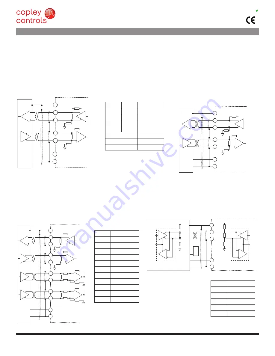
ssI absolute encoder
The SSI (Synchronous Serial Interface) is an interface used to connect
an absolute position encoder to a motion controller or control system.
The XPC drive provides a train of clock signals in differential format to
the encoder which initiates the transmission of the position data on the
subsequent clock pulses. The polling of the encoder data occurs at the
current loop frequency (16 kHz). The number of encoder data bits and
counts per motor revolution are programmable.
The hardware bus consists of two signals: SClk and SdaTa. data is sent
in 8 bit bytes, lSb first. The SClk signal is only active during transfers.
data is clocked out on the falling edge and clock in on the rising edge of
the Master.
biss absolute encoder
biSS is an - open Source - digital interface for sensors and actuators.
biSS refers to principles of well known industrial standards for Serial
Synchronous Interfaces like SSI, aS-Interface® and Interbus® with
additional options.
Serial Synchronous data Communication
Cyclic at high speed
2 unidirectional lines Clock and data
line delay compensation for high speed data transfer
request for data generation at slaves
Safety capable: CrC, errors, Warnings
bus capability incl. actuators
bidirectional
biSS b-protocol: mode choice at each cycle start
biSS C-protocol: Continuous mode
endat absolute encoder
The endat interface is a Heidenhain interface that is similar to SSI in
the use of clock and data signals, but which also supports analog sin/
cos channels from the same encoder. The number of position data
bits is programmable as is the use of sin/cos channels. use of sin/cos
incremental signals is optional in the endat specification.
absolute-a encoder
The absolute a interface is a serial, half-duplex type that is
electrically the same as rS-485. note the battery which must be
connected. Without it, the encoder will produce a fault condition.
endat sIgnals
absolute-a sIgnals
Note: Single (outer) shields should be
connected at both ends (motor and
drive frame grounds). Inner shields
should only be connected to Signal
Ground on the drive.
ssI,biss sIgnals
Sgnd = Signal Ground
f.G. = frame Gnd
Sgnd = Signal Ground
f.G. = frame Gnd
• absolute a
• Tamagawa absolute a
• Panasonic absolute a format
• Sanyo denki absolute a


