background image

20

33

6. Setting up and connection of the devices

Find a suitable place for mounting from which the area to be monitored can be observed.

A suitable place for mounting has the following features:

As free from dust as possible
Little vibration
Good circulation
There is a mains socket close by.

Select a place for mounting which is not shielded by, for example, reinforced concrete walls, steamed up mirrors 
or metal shelves. There should be no devices with strong electrical fields, such as mobile telephones, radios or 
electrical motors, close to the device.
The above-mentioned occurrences can disturb the wireless signal transmission appreciably or limit its range.

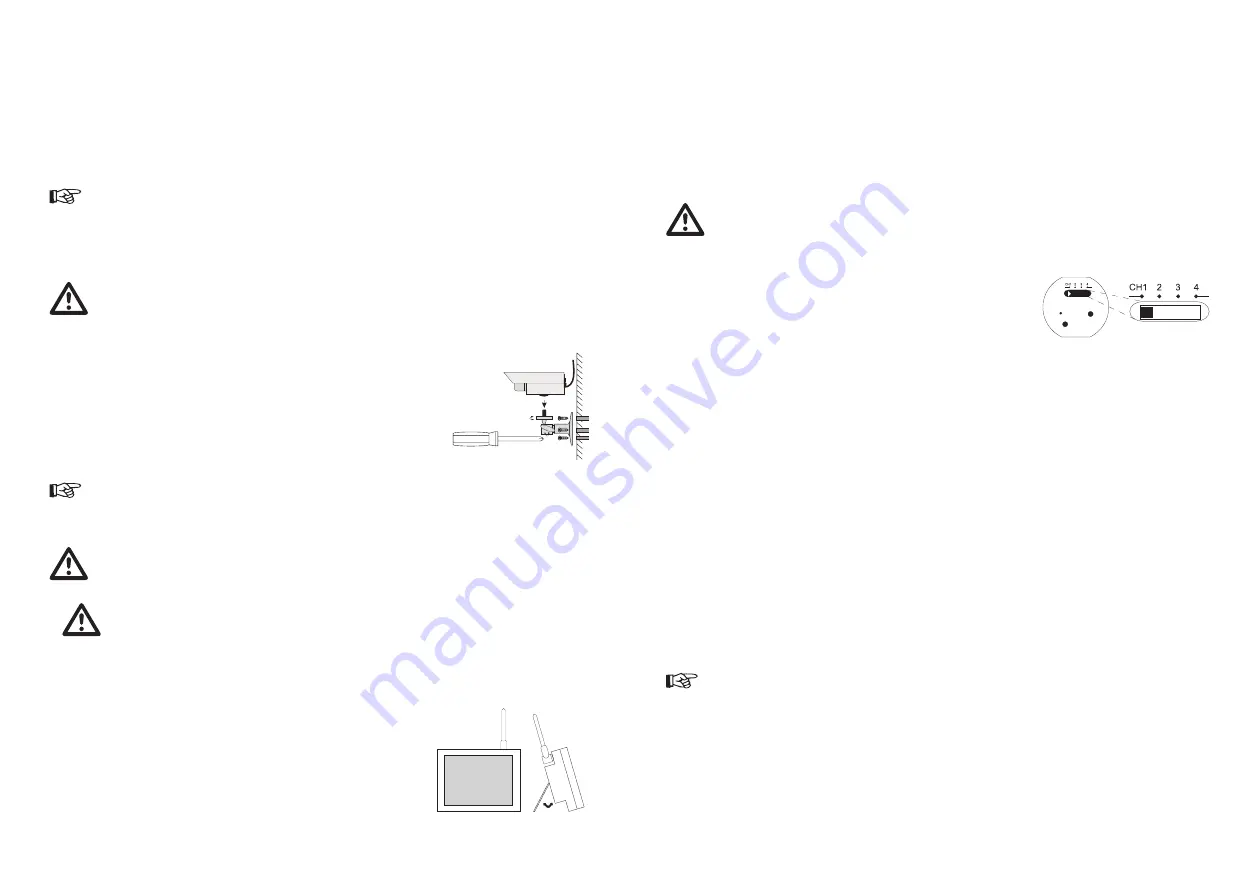
A) Mounting the wireless camera

Before drilling or fastening screws make sure that there are no electric cables, pipes, or wires running 
through the stonework that could be damaged.

Fastening the wall bracket:

Look for a suitable place for mounting (with a socket, if possible)
Screw the wall bracket to a suitable wall or a suitable platform using the supplied 
screws; use dowels if relevant.
Guide the tripod thread of the wall bracket (9) into the thread hold of the camera 
(3) and screw them together.
Align the camera and screw the lateral locking bolt tight.

1.
2.

3.

4.

Do not point the camera directly toward a source of bright sunlight this could lead to over-exposure and an unclear 
picture.

B) Connecting the wireless camera

Apart from the wireless camera, the plug-in power adapter is not weather-proof. Mounting the plug-in 
power adapter in a dry environment (e.g. with weather-proof housing).

Connect the low voltage plug of the power adapter (8) to the power receptacle of the camera (4).

Pay attention to the correct output voltage of 7.5V=!

Insert the plug-in power adapter into a suitable mains socket.
The camera is now ready for use.

C) Setting up the TFT monitor

Position the monitor approx. 1m above the ground for better reception conditions. 
There must be a mains socket in the vicinity of the reception location.
You can tilt the monitor with the fold-up bracket on the rear (26). For attachment to 
a tripod, there is a support on the bottom (25).
In addition, the monitor can be attached to a wall with a matching screw (observe 
the diameter of the screw head!).


1.

2.
3.

7. Mise en service

Raccordez le caméra et l´écran TFT/récepteur comme décrit au chapitre « Installation et raccordement des appareils ».
Allumez l´écran avec le bouton (13) (ON = marche / OFF = arrêt). L´écran est à présent en ordre de marche.
L’antenne du récepteur radioélectrique (18) est réglable afin d’assurer un maximum de qualité de transmission. Faites 
pivoter celle-ci de manière à ce qu´elle se trouve en position verticale.
Modifiez le canal réglé sur la caméra sans fil et sur le récepteur (commutateurs de canaux (7) et (12)) si la transmission 
est perturbée. Voir également le chapitre « Dépannage ».
Pour éteindre les appareils, procédez dans l´ordre inverse de l´activation ou appuyez de nouveau sur la touche ON/OFF 
(13) de l´écran.

En cas de non-utilisation prolongée du système, retirez toujours les blocs d’alimentation de la prise de 
courant.

A) Sélection du canal sur la caméra

Procédez comme suit pour régler le canal de transmission de la caméra sans fil :

Ouvrez d’abord le cache de protection (2) avec un objet pointu (en commençant 
par la gauche, voir la flèche repère).
Prenez un objet pointu tel qu’un stylo bille, puis poussez le sélecteur de canaux 
dans  la  position  désirée  (CH1/2/3/4).  Si  vous  utilisez  plusieurs  caméras,  il 
faut  sélectionner  différemment  les  canaux  des  caméras  car  sinon  il  y  a  des 
chevauchement de signaux.
Refermez ensuite avec précaution le cache de protection (protection contre les 
intempéries).

1.

2.

3.

B) Modes de fonctionnement du récepteur

Le récepteur peut recevoir jusqu´à quatre caméras sans fil. Vous avez donc la possibilité de sélectionner manuellement un 
canal précis ou de surveiller tous les canaux en « mode Scan ».
Une fois allumé, le récepteur se met toujours sur le premier canal radio. Si aucun signal n’est reçu, l’écran aura la couleur 
bleue.

i) Choix manuel de canal :

Pour le réglage manuel des canaux, appuyez sur la touche de réglage des canaux (12) de l´écran TFT. A chaque pression, le 
réglage de canal change (canal 2 – canal 3 – canal 4 - Scan - canal 1..). La diode électroluminescente correspondante (DEL) 
signal le canal choisi dans l´affichage des canaux (21).

ii) Mode Auto Scan :

Si plusieurs caméras sont en service, vous pouvez effectuer un balayage automatique de tous les canaux (mode Scan). 
Appuyez pour cela sur la touche des canaux (12) jusqu´à ce que les quatre DEL s´allument dans l´affichage des canaux. 
Les canaux sont sélectionnés automatiquement les uns après les autres. La durée de commutation des canaux est d’env. 5 
secondes.

Cette fonction convient parfaitement pour effectuer une surveillance réalisée à l´aide de maximum quatre caméras 
sans fil sur un moniteur de surveillance.

1.
2.
3.

4.

5.

Содержание 75 09 69

Страница 1: ...V AC 50 60 Hz Your CONRAD team WICHTIGER HINWEIS IMPORTANT NOTE Dieser Hinweis ist eine Publikation der Conrad Electronic SE Klaus Conrad Stra e 1 D 92240 Hirschau Alle Rechte einschlie lich bersetzun...

Страница 2: ...Hz Uw CONRAD team REMARQUE IMPORTANTE BELANGRIJKE INFORMATIE Cette remarque est une publication de la soci t Conrad Electronic SE Klaus Conrad Stra e 1 D 92240 Hirschau Allemagne Tous droits r serv s...

Страница 3: ...fications sans aucun pr alable Copyright 2007 par Conrad Electronic SE Impressum Deze gebruiksaanwijzing is een publikatie van Conrad Electronic Benelux B V Alle rechten inclusief de vertaling voorbeh...

Страница 4: ...s und Sicherheitshinweise Alle enthaltenen Firmennamen und Produktbezeichnungen sind Warenzeichen der jeweiligen Inhaber Alle Rechte vorbehalten Bei Fragen wenden Sie sich an unsere Technische Beratun...

Страница 5: ...8 6 Aufstellen und Anschlie en der Ger te 9 A Montage der Funkkamera 9 B Anschluss der Funkkamera 9 C Aufstellen des TFT Monitors 9 D Anschluss des TFT Monitors 10 7 Inbetriebnahme 11 A Kanaleinstellu...

Страница 6: ...Symbole Folgende Symbole gilt es zu beachten Das Blitzsymbol im Dreieck warnt vor einem elektrischen Schlag der stark genug ist Personen zu Schaden kommen zu lassen Ein in einem Dreieck befindliches...

Страница 7: ...rkst tten ist der Umgang mit elektrischen Ger ten durch geschultes Personal verantwortlich zu berwachen Beachten Sie auch die Sicherheitshinweise und Bedienungsanleitungen der brigen Ger te die an das...

Страница 8: ...0 toy 100 2 Contrast van 0 toy 100 3 Scherpte van 0 tot 6 4 Kleur vab 0 tot 100 5 Tint van 0 tot 100 6 Video formaat PAL NTSC 7 VCOMA van 0 tot 31 8 VCOMD van 0 tot 31 Blader door het beeldinstellinge...

Страница 9: ...den Deze functie is uitstekend geschikt voor de bewaking van max 4 draadloze camera s op n bewakingsmonitor 1 2 3 4 5 6 Aufstellen und Anschlie en der Ger te Suchen Sie sich einen geeigneten Montageor...

Страница 10: ...nun einsatzbereit Benutzen Sie zur Verl ngerung nur hierf r geeignete abgeschirmte Cinchleitungen Bei Verwendung anderer Kabel k nnen St rungen auftreten Halten Sie die Leitungsl nge m glichst kurz 1...

Страница 11: ...en geschikte schroef mogelijk is let op de diameter van de schroefkop 1 2 3 7 Inbetriebnahme Schlie en Sie die Kamera und den TFT Monitor Empf nger wie unter Kapitel Aufstellen und Anschlie en der Ger...

Страница 12: ...strichenen M lltonne gekennzeichnet Das Symbol bedeutet dass dieses Produkt nicht im Hausm ll entsorgt werden darf Unter dem Symbol steht ein K rzel f r die im Produkt enthaltene gef hrliche Substanz...

Страница 13: ...te gebruiken als het product zichtbaar is beschadigd het product niet meer functioneert en het product tijdens transport te zwaar is belast Neem de apparaten nooit direct in gebruik wanneer deze van...

Страница 14: ...over naar de zwart witmodus Houd er rekening mee dat het strafbaar is om personen zonder hun medeweten en toestemming met deze camera te observeren De beeld en geluidsoverdracht naar de ontvanger ver...

Страница 15: ...46 12 Technische gegevens 47 13 Conformiteitsverklaring 47 Introduction Dear customer Thank you for purchasing this product This product meets the requirements of current European and national guidel...

Страница 16: ...Disposal 23 11 Troubleshooting 24 12 Technical data 25 13 Declaration of conformity 25 Inleiding Geachte klant Hartelijk dank voor de aankoop van dit product Het product voldoet aan de wettelijke nat...

Страница 17: ...switched on The video image then switches to black and white mode to improve sensitivity Please keep in mind that you will render yourself liable to prosecution if you use this camera to keep persons...

Страница 18: ...re switching them on Electric devices are not toys and have no place in the hands of children Make sure that the device is sufficiently ventilated Avoid heavy mechanical stress high temperatures or st...

Страница 19: ...our que ses mati res premi res soient recycl es au mieux Mise au rebut de piles accumulateurs usag s L utilisateurestdansl obligationl galederendrelespilesetaccumulateursusag s Lamiseaurebutdepilesusa...

Страница 20: ...tre Installation et raccordement des appareils Allumez l cran avec le bouton 13 ON marche OFF arr t L cran est pr sent en ordre de marche L antenne du r cepteur radio lectrique 18 est r glable afin d...

Страница 21: ...L cran est pr sent pr t l emploi Utilisez uniquement des c bles Cinch blind s appropri s pour la rallonge L utilisation de c bles autres que ceux sp cifi s peut entra ner des perturbations Veillez une...

Страница 22: ...veillance monitor 1 2 3 4 5 6 Installation et raccordement des appareils Choisissez un emplacement appropri pour le montage d o vous pourrez surveiller l objet d sir Un emplacement appropri a les prop...

Страница 23: ...crease or decrease volume Press VOL to reduce the volume Press VOL to increase the volume To set different image quality Press FUNC button to call up the on screen menu 1 Brightness from 0 to 100 2 Co...

Страница 24: ...iques doit tre surveill e par un personnel responsable sp cialement form cet effet Respecter galement les consignes de s curit et les modes d emploi des autres appareils raccord s la table de mixage E...

Страница 25: ...ctogrammes suivants L clair avec une fl che dans un triangle quilat ral alerte l utilisateur sur la pr sence d une tension non isol e dans le bo tier de l appareil d une valeur suffisante pour provoqu...

Страница 26: ...hnique France T l 0 892 897 777 Fax 0 892 896 002 e mail support conrad fr du lundi au vendredi de 8h00 18h00 le samedi de 8h00 12h00 Suisse T l 0848 80 12 88 Fax 0848 80 12 89 e mail support conrad c...

Отзывы: