background image

4

Opera

tion

(continued)

O p e r a t i o n     l    

4 - 2 5

C o n t r o l   F u n c t i o n   D e s c r i p t i o n s   -   R W
C o n f i g u r a t i o n  

( c o n t i n u e d )

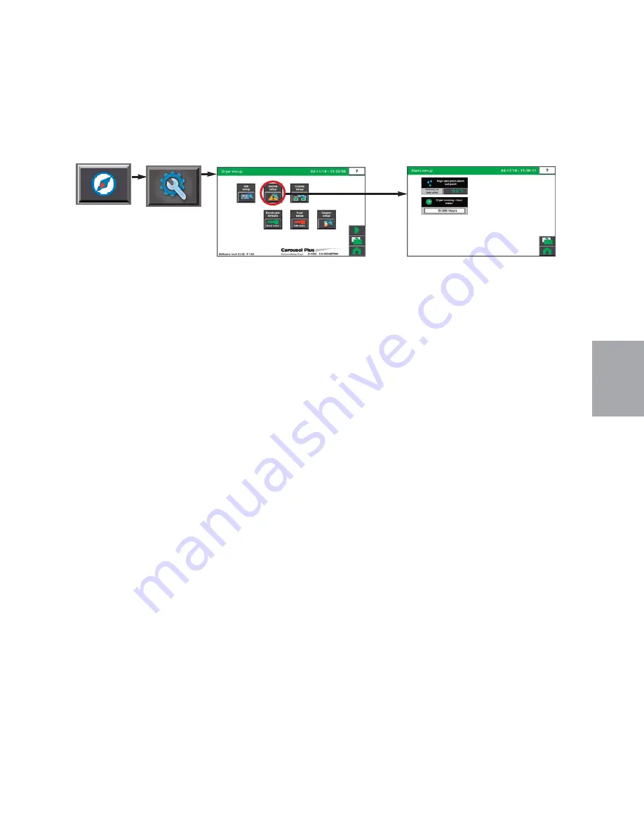
Alarm Setup screen

To access the Alarm Setup screen:

1

Press the Navigation button 

from the Home screen.

2

Press the Set-up (wrench) button 

to get to the Dryer Set-up screen.

3

Press the Alarm Set-up button

.

The Alarm Setup screen provides the user with the ability to adjust setpoints for alarms in
the ResinWorks system. Both passive and shutdown alarms can be modified from these
screens.  The number of alarms visible is dependent on the options installed.

NOTE:

Proper login is required to change these settings.

0

Содержание Carousel Plus D Series

Страница 1: ...es Models 600 through 5000 with DC C TouchViewTM Technology Corporate Office 724 584 5500 l Instant Access 24 7 Parts and Service 800 458 1960 l Parts and Service 814 437 6861 U S E R G U I D E UGD071...

Страница 2: ...le Name Please record your equipment s model and serial number s and the date you received it in the spaces provided DISCLAIMER Conair nor its employees shall be liable for errors contained in this Us...

Страница 3: ...on 3 3 Positioning the dryer on the floor 3 4 Removing the cable tie from the desiccant wheel W600 1000 models 3 4 Installing the regeneration exhaust cover 3 4 Connecting the Process RTD probe 3 5 Co...

Страница 4: ...tion Stand Alone and ResinWorks Dryer Configuration 4 51 DC C System Security Levels 4 52 Starting the Dryer 4 53 Adjusting the temperature setpoint 4 54 Stopping the Dryer 4 55 Stopping the Dryer in...

Страница 5: ...or material drying troubleshooting 6 17 REPAIR Replacing fuses 6 34 Checking heater solid state relays 6 35 Checking or replacing temperature sensors 6 36 Replacing the regeneration heater 6 37 Replac...

Страница 6: ...iv l Table of Contents...

Страница 7: ...guide is organized 1 2 Using the Carousel Plus Dryer with your system 1 3 Your responsibilities as a user 1 3 ATTENTION Read this so no one gets hurt 1 4 How to use the lockout device 1 6 S E C T I O...

Страница 8: ...ed to help organize the User Guide and call your attention to important information regarding safe installation and operation Symbols within triangles warn of conditions that could be hazardous to use...

Страница 9: ...r Responsibility as a User You must be familiar with all safety procedures concerning installation operation and maintenance of this equipment Responsible safety procedures include Thorough review of...

Страница 10: ...te the equipment at power levels other than what is specified on the machine serial tag and data plate WARNING Voltage hazard This equipment is powered by three phase alternating current as specified...

Страница 11: ...cise caution around exterior surfaces that may become hot during use These include the hopper door frame the exterior of an uninsulated hopper the return air hose and the dryer s process filter housin...

Страница 12: ...To use the lockout device 1 Stop or turn off the equipment 2 Isolate the equipment from the electric power Turn the rotary disconnect switch to the OFF or O position 3 Secure the device with an assign...

Страница 13: ...What is the Carousel Plus Dryer 2 2 Typical applications 2 2 How the dryer System works 2 4 Specifications Carousel Plus D Series Dehumidifying Dryers 2 6 S E C T I O N 2 2 D e s c r i p t i o n Descr...

Страница 14: ...e in the plant Typical Applications 1 Dryer on the floor single hopper with delivery air heat Heater Pack on the hopper or a HTC on a floor stand 2 Dryer on the floor multiple hoppers in central confi...

Страница 15: ...271 to 2267 kg per hour some materials can be run at a higher rate Dewpoints of 40 F 40 C Use the aftercooler when Throughput rates are less than 50 of the dryer s rated capacity You are pre drying m...

Страница 16: ...ugh the material The Cooling Cycle All models except D2400 D4000 and D5000 Regenerated desiccant must be cooled before it rotates back into the process cycle The process blower pushes the process air...

Страница 17: ...2 5 How It Works continued Protected under United States Patent No 7 101 414 and other US and Foreign Patents Pending Power Purge D2400 4000 and 5000 models have a Power Purge cooling fan feature int...

Страница 18: ...Specifications Carousel Plus D Series Dehumidifying Dryers continued See the next page for illustrations 2 6 l Description...

Страница 19: ...2 D e s c r i p t i o n Description l 2 7 Specifications Carousel Plus D Series Dehumidifying Dryers continued B A C...

Страница 20: ...2 8 l Description...

Страница 21: ...the return air inlet and air outlet adapters 3 6 Connecting the main power 3 7 Opening the dryer doors 3 8 Checking for proper air flow 3 9 Connecting the air hoses to a single hopper 3 12 Connecting...

Страница 22: ...tape and plastic 4 Cut and remove the desiccant wheel tie securing the wheel assembly D600 1000 5 Carefully inspect all components to make sure no damage occurred during shipping and that you have all...

Страница 23: ...connect the water pipes to the aftercooler and or optional precooler r Minimum clearance for safe operation and maintenance Refer to the illustra tions below for specific minimum clearance distance C...

Страница 24: ...ng the dryer Depending upon which size dryer you have there may be several cable ties Installing the Regeneration Exhaust Cover The Carousel Plus D Series Dryer s regeneration exhaust cover must be in...

Страница 25: ...should be approximately in the center of the tube Tighten the compression fittings to lock the probe in place 2 Plug the probe s cable into the receptacle labeled setback on the left side of the elec...

Страница 26: ...pallet 2 Locate the bolt patterns on the top of the dryer on top of the return air inlet and air out outlet 3 Position the return air adapter on top of the return air inlet aligning both bolt pat tern...

Страница 27: ...T Always refer to the wiring diagrams that came with your dryer before making electrical con nections 3 Connect the power wires to the three terminals at the top of the power disconnect holder 4 Conne...

Страница 28: ...nels 1 Rotate the locking panel bolt on each dryer panel counterclockwise with a regular screw driver 2 Using the handle lift the panel out and up to remove from the side of the dryer Repeat for each...

Страница 29: ...outlet of the hopper 2 Attach one hose or pipe from the de livery air outlet located on top of the dryer to the inlet of the Heater Pack 3 Secure hoses with clamps The hose clamp should be se cured a...

Страница 30: ...Attach one hose from the return air inlet of the dryer to the return air manifold of the ResinWorks 2 Attach one hose from the delivery air outlet of the dryer to the delivery air manifold of the Resi...

Страница 31: ...your dryer hose connection and the connection on your ResinWorks sled are not the same size you will need to use a hose adapter Contact Conair Parts 1 800 458 1960 NOTE Because the D600 5000 models re...

Страница 32: ...et approximately half way down from the end of the dry air delivery outlet 2 Place hose adapter inside high temperature gasket flush to the dryer outlet secure with pressure clamp 3 Attach the hopper...

Страница 33: ...sed it should be mounted on the inlet line Conair recommends that both the supply and return water lines have a shut off valve 2 Connect the water discharge or return line to the aftercooler or precoo...

Страница 34: ...charge or return line to the aftercooler or precooler outlet IMPORTANT Turn the water off when the dryer is not in use to prevent condensation aftercooler inlet aftercooler outlet 2TIP Make the water...

Страница 35: ...tion This powers up the control and the display will illuminate 2 From the Home Screen press the Navigation button 3 Press the Set up button wrench 4 Press Right Arrow button continued OFF O ON I WARN...

Страница 36: ...dryers are equipped with centrifugal delivery air blowers WARNING All wiring discon nects and fuses should be in stalled by qualified electrical technicians in accordance with electrical codes in you...

Страница 37: ...housing 10 If airflow is incorrect disconnect power follow proper lockout pro cedures and reverse the leads at the regeneration blower motor WARNING All wiring dis connects and fuses should be instal...

Страница 38: ...he Hopper If you have a Conair loader or vacuum receiver you can use the flange and mounting clips provided on the top of the hopper Refer to the manuals that came with your specific receiver or loade...

Страница 39: ...neration and process blowers turn on The regeneration heater turns on The process heater will energize if configured as a stand alone dryer The dryer s desiccant wheel starts turning If the desiccant...

Страница 40: ...3 8 l Installation...

Страница 41: ...on 4 15 Operation Stand Alone Dryer Configuration 4 31 Control functions flow chart 4 32 Control function descriptions Stand Alone configuration 4 38 General Operation Stand Alone and ResinWorks Dryer...

Страница 42: ...with a Resin Works dryer with multiple hoppers a central dryer with separate heat source to multiple hoppers or as a stand alone dryer with heater pack at a single hopper Once this factory configurati...

Страница 43: ...reens Navigate through the DC C control screens by touching any navigation buttons continued Navigation Buttons Touching the navigation buttons will take the user to the control screen se lected 4 O p...

Страница 44: ...list of user passwords Set points can be entered within fields with raised beveled edges with green values Values shown within flat rectangles are actual values and can not be changed Set point Field...

Страница 45: ...reens continued All beveled grey buttons on the DC C control screen are selectable and will direct you to an other screen At any point pressing the Home button will return you to the home screen 4 O p...

Страница 46: ...button Visible when installed Image reflects the current operating state of the loader Dryer Settings button Go to the Dryer Settings Selection screen Stop Button Below is a screen from the DC C while...

Страница 47: ...en flow charts screen descriptions and basic operation describe the operation of the dryer when factory configured as a ResinWorks dryer attached to multi ple hoppers or as a central dryer attached to...

Страница 48: ...Control Function Flow Charts From the Home screen Home Navigation Dryer Settings Help Active Alarms Login 4 8 l Operation...

Страница 49: ...4 O p e r a t i o n Control Function Flow Charts From the Navigation screen Navigation Hopper Selection Operation l 4 9 Dryer Settings Dryer Setup...

Страница 50: ...tion Control Function Flow Charts From the Navigation screen Navigation Active Alarms Alarm History Dryer Settings Material Recipes Maintenence Schedule Trend Screen Auto Start Stop Settings Loader Se...

Страница 51: ...ation l 4 11 Control Function Flow Charts From the Setup screen Navigation Comm Set up RW Dryer Setup after pressing wrench Hopper Set up User Set up HMI Set up Pop up from edit VNC button Alarm Set u...

Страница 52: ...4 12 l Operation Continued Control Function Flow Charts From the Alarm screen Home Alarms Acknowledge all Alarms...

Страница 53: ...Operation l 4 13 continued Control Function Flow Charts From the Trend Selection screen Dewpoint Navigation Temperature NOTE You can view additional trend screens on the optional ResinWorks HMI scree...

Страница 54: ...4 14 l Operation Control Function Flow Charts From the Login Logout screen Home Login Screen 3...

Страница 55: ...s the user to start or stop the dryer The user can also view the other system parameters on the Navigation screen view alarms view hopper settings or log in by pressing the applicable buttons on the r...

Страница 56: ...Hopper Setup Selection screen provides the user with the list of enabled hoppers If the list is empty or does not show the proper number of hoppers Setup has not been completed yet See Operation sect...

Страница 57: ...d using the red stop and green start buttons NOTE Depending on which options your dryer has been configured with whether or not you have the Drying Monitor enabled and your user level your screens and...

Страница 58: ...tions your dryer has been configured with whether or not you have the Drying Monitor enabled and your user login level your screens and icons may appear different For example if your ResinWorks system...

Страница 59: ...n 1 Press the Navigation button from the Home screen 2 Press the ResinWorks Dryer Settings button The ResinWorks Dryer Settings screen provides the user with the ability to enable or disable options T...

Страница 60: ...Auto Start and Auto Stop 1 Press the Enable button to enable DryerAuto Start 2 Press the Enable button next to each day of the week you would like to set the Auto Start time 3 Set the Auto Start time...

Страница 61: ...tion screen 3 Press the individual Hopper Button to go to the Hopper Settings screen for that in dividual hopper The Hopper Set up screen provides the user with the list of enabled hoppers Selecting t...

Страница 62: ...entered hopper name up to 16 characters 2 Use the keypad to enter your new hopper name Hopper names can be up to 16 char acters in total length 3 Press the enter button when complete 4 Use steps 1 th...

Страница 63: ...qualified personnel should at tempt changes Improper setting sequence or values will result in loss of communications Always record your new settings before making any changes Always set the PLC firs...

Страница 64: ...t screen To access the I O test screen 1 Press the Settings button from the Navigation screen 2 Press the right arrow 3 Follow the Help Screen Instructions The Dryer I O screen provides the user with...

Страница 65: ...2 Press the Set up wrench button to get to the Dryer Set up screen 3 Press the Alarm Set up button The Alarm Setup screen provides the user with the ability to adjust setpoints for alarms in the Resi...

Страница 66: ...n alarm if the demand is not satisfied in that number of cycles When drying monitor is installed low and high temperature alarms is visible and can be set at the same or different points in the dry in...

Страница 67: ...p immediately to live data The user can also touch any point on the trend line and the display will show the data reading date and time for that spot in the trend Scroll to the beginning or end of the...

Страница 68: ...eel Inlet Temperature The Dry Air Temperature Trending screen shows values sampled every 15 seconds Each colored line represents a pen or variable being trended Up to 14 days of data is recorded and a...

Страница 69: ...s values sampled every 15 seconds Each colored line represents a pen or variable being trended Up to 14 days of data is recorded and available for review The scroll buttons near the bottom of the scre...

Страница 70: ...rms Silence and Acknowledge Alarms Reset All Alarms or clear individual alarms If you select the alarm check the box or touch the word select to select all the selected alarms will also be acknowledge...

Страница 71: ...flow charts screen descriptions and basic operation describe the operation of the dryer when factory configured as a stand alone dryer attached to a single hopper with a Conair Heater Pack Operation S...

Страница 72: ...Control Function Flow Charts From the Home screen 4 32 l Operation Home Navigation Dryer Settings Help Active Alarms Login Logout...

Страница 73: ...t i o n Control Function Flow Charts From the Navigation screen Operation l 4 33 Navigation Active Alarms Alarm History Dryer Settings Material Recipes Loader Settings Maintenon Schedule Auto Start St...

Страница 74: ...4 34 l Operation Control Function Flow Charts From the Alarm screen Home Alarms Alarm Message Pop up...

Страница 75: ...4 O p e r a t i o n Continued Operation l 4 35 Control Function Flow Charts From the Trend Selection screen Drying Monitor when installed Dewpoint Navigation Heater on Time Energy Use Temperature...

Страница 76: ...nued Control Function Flow Charts From the Setup screen Navigation Comm Set up Dryer Setup after pressing wrench Loader Set up User Set up HMI Set up Pop up from edit VNC button Alarm Set up Dryer I O...

Страница 77: ...4 O p e r a t i o n Continued Operation l 4 37 Control Function Flow Charts From the Login Logout screen Home Log in 6...

Страница 78: ...n 1 Press the Dryer Navigation button located on the home screen The Dryer Navigation screen provides the user with access to dryer set up screens NOTE On this Home screen live data is displayed Data...

Страница 79: ...eratures if equipped If the user is logged in at the proper security level setpoint changes can be made to Manual Setback Control Dewpoint Control Setpoint The user can also view the other system para...

Страница 80: ...configured with and whether or not you have the Drying Monitor enabled your screens and icons may appear dif ferent 0 NOTE Live data is displayed as colored text inside a box Set points boxes are beve...

Страница 81: ...y to enable or disable options This screen allows you to change the status of Date and Time English or Metric Measured Voltage Material Drying Temperature Setpoint Material Residence Time Setpoint NOT...

Страница 82: ...of the week To setup Auto Start and Auto Stop 1 Press the Enable button to enable DryerAuto Start 2 Press the Enable button next to each day of the week you would like to set the Auto Start time 3 Se...

Страница 83: ...Press the Wrench button to open the Dryer Set up button 3 Press the Alarm Set up button to open the Alarm Set up screen The Alarm Setup screen provides the user with the ability to enable disable and...

Страница 84: ...urchased with the dryer Possible tests are Delivery air blower Regen blower Regen heater jog Wheel motor Alarm horn red light Heater isolation contactor Delivery air heater jog Alarm yellow light Alar...

Страница 85: ...iew the current alarms 3 Decide if you want to Acknowledge Alarms Silence and Acknowledge Alarms Reset All Alarms or clear individual alarms If you select the alarm check the box or touch the word sel...

Страница 86: ...net settings requires the Admin login Only qualified personnel should at tempt changes Improper setting sequence or values will result in loss of communications Always record your new settings before...

Страница 87: ...the screen allow the user to scroll back to an earlier time or forward to the present time or jump immediately to live data The user can also touch any point on the trend line and the display will sh...

Страница 88: ...ith the locations are Orange Regeneration Temperature within the dryer Pink Wheel Inlet Temperature Blue Material Drying Temperature Yellow Hopper Outlet Temperature The Dry Air Temperature Trending s...

Страница 89: ...or probe The Drying Monitor Trending screen shows values sampled every 15 seconds Each colored line represents a pen or variable being trended Up to 14 days of data is recorded and avail able for revi...

Страница 90: ...4 50 l Operation...

Страница 91: ...4 O p e r a t i o n General Operation Stand Alone and ResinWorks Dryer Configuration Operation l 4 51...

Страница 92: ...er in it representing your current security level Pressing the Login button again will log the user out of the system Also inactivity for 10 minutes will log you out of the control The control will re...

Страница 93: ...r graphic to start the dryer system OFF O ON I ResinWorks configuration Stand alone configuration Operation l 4 53 NOTE The Start and Stop buttons will appear as grey when that function is not availab...

Страница 94: ...d the hopper outlet temperature Increasing the hopper outlet temperature will increase the pressure drop in filters due to the velocity of the air increas ing Increasing air temperature decreases its...

Страница 95: ...etpoint 2 Observe the dryer status changing to Stopping or Shut down 3 Wait until the dryer status changes to Standby which will alert you that the cooldown setpoint has been reached Depending on your...

Страница 96: ...ters from power After shutting down for an emergency an thorough inspection of the dryer and drying system should be performed prior to using the dryer checking for damage to components due to the dry...

Страница 97: ...the regeneration filter 5 8 Cleaning the aftercooler coils 5 9 Inspecting hoses and gaskets 5 11 Cleaning the precooler coils 5 12 Cleaning the volatile trap on the demister W600 W1000 5 13 Cleaning t...

Страница 98: ...osition and tighten loose hose clamps See Maintenance section entitled Inspecting Hoses and Gaskets r If equipped Open volatile drain valve to remove volatiles and residue that may have accumulated Pl...

Страница 99: ...table instrument See Maintenance section entitled Checking the Dewpoint r Measure current draw on all three 3 legs of heater wires for the delivery air and regen heater This is to ensure that the heat...

Страница 100: ...ter to the dewpoint check port on the rear panel of the dryer 2 Turn on the portable instrument and ensure there is positive airflow through the sensor 3 Monitor the readout and allow ample time for i...

Страница 101: ...om the hopper This can be done by conveying material out of the hopper or by manually emptying material using a bucket or a vacuum 2 Open the hopper door and wipe out the inside of the hopper CAUTION...

Страница 102: ...by using an indus trial vacuum for the outside and compressed air from the inside Follow all company and local com pressed air procedures If the filter has been used and cleaned several times it proba...

Страница 103: ...lacethecleanfilterinthedryer and use the wing nut and washer to hold the filter in place Make sure the filter is completely seated against the back of the filter housing 4 Placecovercap andusethelatch...

Страница 104: ...seated in the filter housing NOTE Dirty or clogged re generation filters are the leading contributor of dry ers not reaching desired dewpoints 0 CAUTION Wear eye protection If you use compressed air t...

Страница 105: ...u process 1 Stop the dryer and lockout the main power 2 Turn off the water flow close valves to the water supply line and return line Disconnect supply and return lines 3 Remove the bolts securing the...

Страница 106: ...ion of the gasket If it is damaged replace the gasket 7 Reassemble by repeating the steps in reverse order 8 Connect the water supply line and return lines 9 Open valves to return water to the system...

Страница 107: ...can allow moisture to seep into the closed loop drying system 1 Follow the hose routing of all the hoses within the dryer and inspect all hoses clamps fittings and gaskets 2 Tighten any loose hose cla...

Страница 108: ...precooler by pulling it out of the precooler housing 5 Clean the assembly using a mild soap and water Let the assembly dry thoroughly before installation NOTE In cases of heavy volatiles steam cleanin...

Страница 109: ...e of solvents such as acetone may be necessary Be sure to test a small area with the solvent you have selected to be sure there is no adverse reaction 5 Insert the demister carefully back into the hou...

Страница 110: ...and water Let the assembly dry thoroughly before installation NOTE In cases of heavy volatiles steam cleaning pressure washing or the use of solvents such as acetone may be necessary Be sure to test...

Страница 111: ...clean the screen to keep dirt from accumulating on the screen 1 Turn the dryer off 2 Using a clean dry soft cloth wipe the screen gently to remove any dust or dirt If stubborn spots remain a gentle c...

Страница 112: ...5 16 l Maintenance...

Страница 113: ...6 11 Additional alarms 6 14 Dewpoint troubleshooting 6 16 Poor material drying troubleshooting 6 17 REPAIR Replacing fuses 6 34 Checking heater solid state relays 6 35 Checking or replacing temperatu...

Страница 114: ...alarm descriptions later in this section 3 Press the Alarm History button to view a history of alarms or press the Silence and Ack All Alarms button to acknowledge the alarms If the alarm reappears t...

Страница 115: ...troubleshooting or performing repairs CAUTION Hot surfaces Always protect yourself from hot surfaces inside and outside of the dryer and hopper Troubleshooting l 6 3 Before Beginning continued o Find...

Страница 116: ...Plus Dryer System or its components Shutdown alarms for the components within the Carousel Plus Dryer System A problem can trigger two types of alarms Shutdown The dryer has automatically shut down b...

Страница 117: ...tton when the alarm occurs 2 Find the error message in the diagnostics table of the following troubleshooting sec tion of this manual or the troubleshooting section of the applicable component user ma...

Страница 118: ...main screen to access the alarm history and note the newest alarm s 4 Press the Acknowledge All Alarms button 5 After correcting the problem take note of the problem If the problem was not solved the...

Страница 119: ...is blocked or the air hoses are loose The regeneration blower is not running or running in the wrong direction The isolation contactor failed in the closed position The heater solid state relays SSRs...

Страница 120: ...ir lines are restricted or loose The delivery blower is not running or is running in the wrong direction The delivery heater output on the board has failed or the output fuse has failed Delivery setpo...

Страница 121: ...has failed Solution Locate and remove any airflow restric tions Tighten any loose hoses Correct the cause of the non running blower blown fuse etc or reverse the rotation of the blower Replace the is...

Страница 122: ...e process protection RTD has failed The control board has failed Solution Make sure the RTD temperature probe tip is in the center of the hopper inlet tube Correct the cause of the non functioning blo...

Страница 123: ...olution Check for air flow blockages or loose hoses between the outlet of the dryer and the inlet of the hopper Straighten any crimps in the hoses Tighten any loose hoses The dryer and the hopper shou...

Страница 124: ...ations boards have failed One of the three power wires are out of phase A fuse has blown Phase detection board has failed Internal control board problem Solution Check the RTD plug connection and make...

Страница 125: ...lower for me chanical failure and free rotation Re place if necessary Allow the overload to reset then try to restart the dryer Disconnect and lock out main power Check the delivery air blower for ele...

Страница 126: ...ck the regeneration blower for me chanical failure and free rotation Re place if necessary Allow the overload to reset then try to restart the dryer Disconnect and lock out main power Check the regene...

Страница 127: ...ition The output on the board has failed The regeneration heater has failed The regeneration RTD is loose or has fallen out The regeneration blower is not running The output on the control board has f...

Страница 128: ...generation heater The hopper does not contain enough material You are drying at a high drying tempera ture above 120 F 49 C or running at low throughputs The aftercooler does not have enough water The...

Страница 129: ...g and hose connections to the sensor secure if needed Remove the air flow restrictions dirty filters etc Check the desiccant for contamination replace if needed Install plasticizer volatile trap for s...

Страница 130: ...failed The control board has failed The wheel motor is not turning The belt tensioner is loose or the belt is slipping The regeneration heater is not working Solution Remove and clean or replace the p...

Страница 131: ...Delivery air heater has failed Solution Replace the failed solid state relays SSRs Check the heater fuses and resistance across each leg of the delivery air heater Replace the board Check the process...

Страница 132: ...n and tighten if needed Replace the setback RTD Replace the control board Passive Alarms If an alarm occurs a red dialog box is displayed on the dryer s touch screen control The dryer continues to ope...

Страница 133: ...g connection and make any necessary repairs Check the plug connection and tighten if needed Replace the regeneration outlet RTD Replace the control board See Troubleshooting section entitled Passive a...

Страница 134: ...rol board A sensor is disconnected or malfunction ing The dryer is currently in a stage where stopping or starting the dryer is not avail able Loose connection or wiring is not cor rect Dryer board fa...

Страница 135: ...olution Check that all jumpers are in their proper place Check to see if the dewpoint sensor and other sensors are connected properly Disconnect the ribbon cable connect ing any analog option boards t...

Страница 136: ...Parts at 800 458 1960 for the addition of a volatile trap Verify dryer dewpoint readings with a calibrated portable dewpoint meter Replace analog option board or sensor Dewpoint Troubleshooting Under...

Страница 137: ...r Conair dryer is equipped with the Setback feature you should familiarize yourself with it and make use of it If not you may want to contact Conair to determine if it can be added to your dryer A maj...

Страница 138: ...failure Solution Refer to the drying specifications for your material and adjust the setpoint to the recommended setpoint If your dryer has the Setback option make sure it is not active unless you hav...

Страница 139: ...ion Make sure there is an adequate supply of material to feed the loader on top of the drying hopper Correct any problems with the convey ing system that may be preventing your loader from filling the...

Страница 140: ...leshoot ing continued Airflow The airflow in the process drying circuit must be adequate to carry and distribute the heat throughout the entire bed of material inside the hopper If the air flow is too...

Страница 141: ...air temperature is measured at the inlet to the process blower Poor desiccant performance Solution Replace or check defective heaters fuses etc Clean or replace the regeneration filter Ensure the reg...

Страница 142: ...uses RTD sensors to monitor the temperatures of the return air the regeneration outlet and the regeneration inlet Your dryer may have optional a sen sor for delivery air process protection and or set...

Страница 143: ...ead 0 zero When relay is de energized LED off full voltage should be measured across the relay When relay is off if voltage reads zero relay is bad and needs replaced Re peat this procedure for each r...

Страница 144: ...the top and bottom of the regeneration heater tube Remove and check the bottom heater hose for loose debris or fragments these frag ments can damage the newly installed heater if not removed 6 While...

Страница 145: ...mp 11 Connect the hoses to the top and bottom of the heater tube and secure them with hose clamps 12 Connect the high temperature switch wires to the quick disconnects near the heater tube 13 Route th...

Страница 146: ...ers lower clamp is attached to a bracket that is mounted to the desiccant wheel assembly loosen clamp to remove it from the bracket Remove and check the bottom heater hose for loose debris or fragment...

Страница 147: ...heater tube bracket that was removed in Step 5 10 Connect the high temperature switch cable to the quick disconnect 11 Route the heater power wires into the junction box and connect them to the suppl...

Страница 148: ...iation when measured leg to leg and high resistance from each leg to ground Readings other than this indicate a defective heater 4 Disconnect the high temperature switch cables at the quick disconnect...

Страница 149: ...nal insulation over the new heater or if the insulation was cut for re moval wrap the cut insulation sleeve around the new heater tube and secure it with heat tape 10 Make sure the cable end of the ne...

Страница 150: ...n off the water supply to the aftercooler and disconnect the water lines from the aftercooler 6 Remove the four bolts securing the aftercooler assembly to the cabinet frame 7 Using an overhead crane o...

Страница 151: ...g the four bolts you removed earlier 12 Verify position of the desiccant wheel assembly and bolt it in place 13 If the aftercooler is being used reconnect the water lines 14 Reconnect or reinstall all...

Страница 152: ...e securing bolts 4 Note the position of all the hoses RTDs and wiring connections then remove or disconnect these from the desiccant wheel assembly 5 Remove the bolts securing the desiccant wheel asse...

Страница 153: ...el to ensure optimum performance 1 Stop the dryer disconnect and lockout the main power 2 Remove the upper side panels from both sides of the dryer 3 Remove the side panels from both sides of the desi...

Страница 154: ...ve the tension on the drive bolt by loosening the nut above the tension spring until the belt can be slipped off the motor sprocket 5 Remove the belt from the motor sprocket 6 Move to the other side o...

Страница 155: ...t of cardboard inside the housing on each side to protect the gaskets before you insert the new wheel 9 Place the new wheel into the housing and then pull the pieces of cardboard out from between the...

Страница 156: ...or pulley then remove the pulley from the motor 6 Remove the screws securing the motor to the upper and lower bracket and remove the motor 7 Secure the new motor to the bracket 8 Install the pulley on...

Страница 157: ...on nection to the motor 5 While noting the number of turns relieve the tension on the drive bolt by loosening the nut above the tension spring until the belt can be slipped off the motor sprocket 6 Un...

Страница 158: ...11 With the access panel still removed connect the power to the dryer and start it Ensure the wheel turns in the correct direction If the belt appears to be slipping it may be necessary to increase t...

Страница 159: ...from the serial tag and parts list numbers for your particular equipment Service personnel will need this information to assist you r Make sure power is supplied to the equipment r Make sure that all...

Страница 160: ...he equipment and perform alterations or adjustments to satisfy performance claims Charges for such inspections and corrections will be waived unless failure to meet warranty is due to misapplication i...

Страница 161: ...380VAC 4 1 5 1 D1600 400VAC 4 1 5 1 D1600 460VAC 6 1 5 1 D1600 575VAC 8 1 5 1 D2000 380VAC 6 1 5 2 D2000 400VAC 6 1 5 2 D2000 460VAC 6 1 5 2 D2000 575VAC 8 1 5 2 D2400 380VAC 6 1 5 2 D2400 400VAC 6 1...

Страница 162: ...r HP Regen Motor HP Process Heater kW Regen Heater kw Refer to drawing 188674 D600 7 5 0 5 38 15 D800 7 5 0 5 38 19 15 D1000 7 5 0 5 38 19 15 D1300 10 0 5 38 38 19 D1600 15 0 5 38 38 19 D2000 20 0 5 3...

Страница 163: ...ing Monitor DM 4 For use with D Series Dryers with DC C Control Corporate Office 724 584 5500 l Instant Access 24 7 Parts and Service 800 458 1960 l Parts and Service 814 437 6861 Appendix Appendix l...

Страница 164: ...oading device installed to the top of the drying hopper to assure that it does not attempt to load the hopper with material 2 Perform the proper shutdown sequence to the connected dryer or drying syst...

Страница 165: ...eters Typical Applications The Drying Monitor is ideal for applications that require strict monitoring of the drying process to meet product quality specifications The DM can also aid in the preventio...

Страница 166: ...eater failure excess throughput for that hopper size unresponsive loading over capacity drying and many other condi tions that are likely to produce scrap and waste time energy and material The DM wil...

Страница 167: ...for probe installation according to instruc tions supplied in this manual RTD junction boxes link the cable from the hopper probe into the ModBus communications interface and back to the local heat c...

Страница 168: ...n the DM temperature probe and is positioned at the bottom of the diffuser cone section T6 is the upper most temperature sensor in the DM temperature probe and is located near the top of the hopper wh...

Страница 169: ...pping 36 16 SPECIFICATION NOTES Specifications may change without notice Check with a Conair representative for the most current information The DM is also available as a independent option with its o...

Страница 170: ...make sure no damage occurred during ship ping and that you have all the necessary hardware 4 Take a moment to record serial numbers Also record the drying hopper s model number and specifications This...

Страница 171: ...hopper as near as possible to the hopper probe and if possible not directly above the hopper to minimize transmitted heat from the hopper to the junction box Stay clear of load ing equipment that may...

Страница 172: ...for the probe l Select Mounting Method 1 if you purchased a new Conair CH series drying hop per equipped with a factory installed coupling for the probe l Select Mounting Method 2 if you are installin...

Страница 173: ...ition the connector in such a way as to avoid interference of the cable with the loader etc Use a wrench to tighten the nut so that it covers the threads Sleeve Connector Coupling Tools for Installati...

Страница 174: ...e with the loader etc Use a wrench to tighten the nut so that it covers the threads 9 Thoroughly clean the inside of the hopper to remove any debris left from installation of the probe Four 10 32 UNF...

Страница 175: ...around the probe so that it will fit through the hole NOTE If the angled probe is used the bend dog leg in the probe must be oriented so that it is angled in toward the center of the hopper Adapter p...

Страница 176: ...correct size The probe should extend from just above the top of the hopper into the hopper with the tip approximately in line with the bottom edge of the diffuser cone 11 Push the compression sleeve i...

Страница 177: ...routed away from heated surfaces material conveying lines or moving equipment and not run in parallel to three phase power lines Support each cable as needed to prevent strain on the con nectors Care...

Страница 178: ...ased on the specific screen From the Overview page the buttons include A Hopper Selector Button for viewing of all hoppers included in the sys tem up to 15 An Alarm Log Button for viewing of not only...

Страница 179: ...u are currently looking at Login Logout button This button is used to log in or log out as a user System status This area displays mes sages to let you know the current status of the dryer Dryer Setti...

Страница 180: ...ionality of your DC C dryer control the DC C must be set to communicate to your installed Drying Monitor hardware To set up the DC C to use the DM 1 Press the Dryer Seup button The System Settings scr...

Страница 181: ...ction screen any hopper can be spotlighted by pressing its icon and a detailed view of that hopper will appear and its name will be shown in the green stripe From the detailed hopper view you will see...

Страница 182: ...ow Range 5 15 seconds Alarm Setpoint and Location Low and high temperature alarms can be set at the same or different points in the drying hopper Selecting the at T pushbutton changes the locatin the...

Страница 183: ...the specific point where the material will see that process temperature for 4 hours or the remainder of its travel through the hopper on its way to processing The drying zone is between sensor T1 the...

Страница 184: ...el Number RTD T5 is likely at a 440 lb fill level 35 ft3 x 12 6 RTD T4 is at the 320 lbs level 35 ft3 x 9 15 This position is at the 3 4 point of the material load RTD T5 is closest to the desired mon...

Страница 185: ...icient to dry the material The Alarm Setpoint is preset at band midpoint NOTE If the sensed temperature falls below the Alarm Setpoint for a longer period than the Delay Time default is five minutes t...

Страница 186: ...alarm notification can be adjusted on the Set up screen Remote Heat Source Procedure 1 Press setup button from the home screen logged in at appropriate level to see setup button 2 Press Alarm setup bu...

Страница 187: ...DM The Basics Alarm Setpoint continued From Stand Alone Dryer Screen Procedure 1 Press the Navigation button 2 Press the setup button wrench 3 Press the alarm setup button 4 Set Drying Monitor high a...

Страница 188: ...5 F from 225 F If the DM is being used on a central drying with an HTC or Heater Pack the process temperature on that hopper must be changed 2 If material characteristics require a parameter adjustmen...

Страница 189: ...i cating that material is ready If the temperature drops below 95 of setpoint the residence timer stops until it returns to the set point range It then continues counting up toward the desired residen...

Страница 190: ...183 1 62 2 4 13 75221183 1 18 2 3 18 75221183 0 78 2 2 23 75221183 0 35 2 1 28 75221183 0 14 CH RW 14 3 14 3 5 9 25 2 87 3 4 17 25 2 17 3 3 25 25 1 47 3 2 33 25 0 80 3 1 41 25 0 16 CH RW 14 4 14 4 5 8...

Страница 191: ...58 8 14 12 3 31 83 5 39 12 2 21 08 2 72 12 1 10 33 0 52 CH RW 24 15 24 15 5 11 13 12 60 15 4 24 63 9 14 15 3 38 13 5 69 15 2 51 63 2 32 15 1 65 13 0 57 CH RW 24 18 24 18 5 10 88 15 56 18 4 27 38 11 35...

Страница 192: ...52 85 70 3 43 98 38 93 70 2 54 48 25 01 70 1 64 98 15 68 CH 54 85 54 85 5 23 98 80 12 85 4 36 98 62 89 85 3 49 98 45 67 85 2 62 98 28 52 85 1 75 98 15 17 CH 54 99 54 99 5 26 98 92 93 99 4 42 73 73 05...

Страница 193: ...53 40 215 3 82 48 108 25 215 2 106 73 63 16 215 1 130 98 20 73 CH 64 248 64 248 5 34 48 229 24 248 4 62 48 177 12 248 3 90 48 124 99 248 2 118 48 72 86 248 1 146 48 23 49 CH 74 245 74 245 5 30 98 180...

Страница 194: ...ume of to calculate the bulk density of your material 2 Weigh the empty container and record the weight 3 Fill the container with your material level it off at the top with a straight edge 4 Weigh the...

Страница 195: ...DM probes will rise towards the drying set point temperature starting with T1 If processing does not start no material taken away from the hopper eventually all the probes with the possi ble exception...

Страница 196: ...ssing can begin when the alarm location sensor typically T3 or T4 has stabilized at the drying temperature setpoint for approximately 50 of the required residence time Example If the material drying t...

Страница 197: ...the loading system being used typically dictate the size of the no material area at the top of the hopper depending upon where the demand switch for loading more material is located how far into the h...

Страница 198: ...increase and align with the process temperature The stopped material now has time to more fully absorb drying heat If material flow increases an increase in throughput the difference in temperature r...

Страница 199: ...consuming mate rial level in the hopper decreases T4 will eventually follow especially if it also becomes exposed to air and not material NOTE Successful drying is in jeopardy if the material supply...

Страница 200: ...is a reaction to a quantity of cold material being introduced into the hopper following a lapse of automatic loading This drop can be compared to a cold front of material moving down through the hoppe...

Страница 201: ...temperature to the drying hopper initially show up as a reduction in T1 and T2 temperature readings Frequently this reduction does not display immediately due to the residual heat of the material The...

Страница 202: ...gh the hopper The remaining probes will also decrease in temperature as the problem contin ues even though T1 and T2 continue to display levels close to the process temperature This can be a very grad...

Страница 203: ...Interpreting Drying Monitor Trend Curves Actual DM Trend Analysis Below is an actual trend analysis used by a PET bottle processor to find the cause of overnight process variations Appendix l C 41...

Страница 204: ...nce is required beyond wiping down and examining for damage whenever the hopper is empty cool and available for inspection In the event of visible damage or non operation replace the probe Do not atte...

Страница 205: ...e hopper and is constantly facing a refreshed supply of material while that material is flowing down and into the process which creates a predictable heat profile for good drying inside the hop per Th...

Страница 206: ...ition Refer to the User Guide that came with your dryer for more information on understanding alarms The information in the alarm notification box on your DC C screen tells you which hopper has trigge...

Страница 207: ...tion Terminating the final RTD Junction Box for properly terminating the last hopper Check all connections and replace cable set s that are damaged Replace the hopper probe Replace the hopper probe Pr...

Страница 208: ...C 46 l Appendix...

Отзывы: