background image

6-14

     Upgrading the Desktop Computer

Writer: Debbie Thomson    Saved by: Alyce Klingler-Castle    Saved date: 06/13/97 5:32 PM

Pages: 37    Words: 5251    Template: c:\msoffice\templates\comm.dot

File Name Ch6.doc    Part Number 270844-002

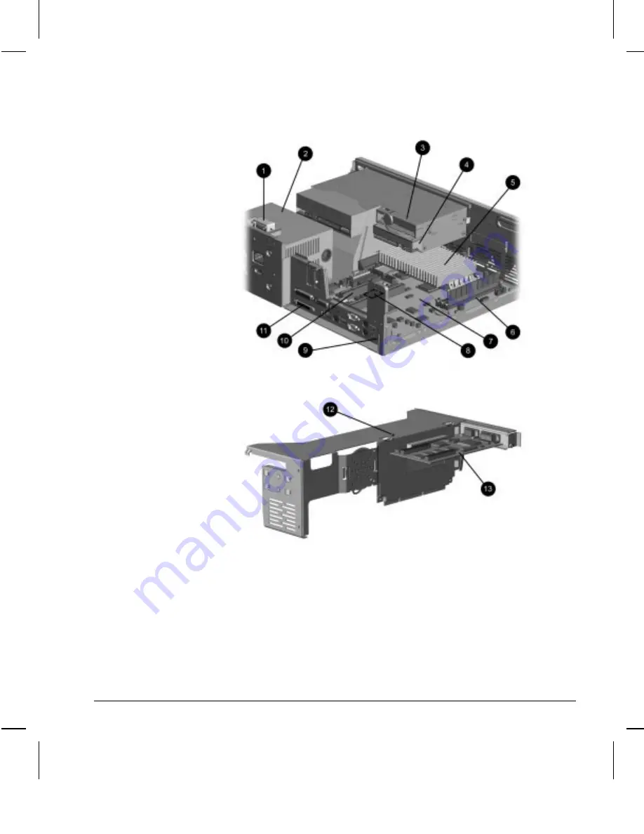
Internal Components in Pentium II–Based Models

Expansion Boards in Pentium II–Based Models

The position of the expansion board cage in this
illustration is for demonstration purposes only. Be sure to
rest the expansion board cage upside down rather than on
either side of the cage.

Содержание 247320-003 - Deskpro 4000 - 5166 Model 2500/CDS

Страница 1: ...REFERENCE GUIDE Compaq Deskpro 4000 Series of Personal Computers Compaq Deskpro 6000 Series of Personal Computers...

Страница 2: ...Writer Debbie Thomson Saved by Debbie Thomson Saved date 06 04 97 9 57 PM Pages 2 Words 179 Template c msoffice templates commnoti dot iii...

Страница 3: ...without prior written consent from Compaq Computer Corporation 1997 Compaq Computer Corporation All rights reserved Printed in the U S A Compaq and Deskpro registered U S Patent and Trademark Office...

Страница 4: ...Writer Debbie Thomson Saved by Debbie Thomson Saved date 06 04 97 9 57 PM Pages 2 Words 179 Template c msoffice templates commnoti dot iii...

Страница 5: ...at the same time the action is represented by the key names and the plus symbol For example Ctrl Alt Delete The names of files are presented in uppercase italic type as shown here FILENAME The names...

Страница 6: ...UTION Text set off in this manner indicates that failure to follow directions could result in damage to equipment or loss of information Text set off in this manner presents clarifying information spe...

Страница 7: ...e to 384 megabytes installed in dual inline memory modules DIMMs Smart Cover Lock a software controllable cover lock High density 3 5 inch 1 44 megabyte diskette drive or 3 5 inch 120 megabyte LS 120...

Страница 8: ...gabytes SGRAM and expandable to 4 megabytes SGRAM or the Matrox Millennium II AGP graphics controller with 4 megabytes WRAM and expandable to 16 megabytes WRAM One Ultra ATA hard drive installed hard...

Страница 9: ...ive only Ejects a loaded diskette 3 Stereo Headphone Jack Connects headphones to the CD ROM drive 4 Headphone Volume Control Adjusts the volume of the CD ROM drive 5 CD ROM Drive Busy Indicator Flashe...

Страница 10: ...Part Number 270844 002 WARNING This equipment is designed for connection to a grounded earthed outlet The grounding type plug is an important safety feature To avoid the risk of electrical shock or d...

Страница 11: ...crophone CD ROM drive models blue colored icon 8 Line In Audio Connector Connects a device that supplies sound such as a tape deck or CD player CD ROM drive models 9 Line Out Audio Connector Connects...

Страница 12: ...r Your Name Saved by Troy Witte Saved date 06 16 97 3 17 PM Pages 15 Words 2504 Template c msoffice templates comm dot File Name Ch1 doc Part Number 270844 002 Minitower Front and Rear Panel Component...

Страница 13: ...in Energy Saver mode 3 Hard Drive Activity Light Turns on when the hard drive is reading or saving data 4 Diskette Drive Activity Light Turns on when the diskette drive is reading or saving data 5 Ste...

Страница 14: ...dot File Name Ch1 doc Part Number 270844 002 WARNING This equipment is designed for connection to a grounded earthed outlet The grounding type plug is an important safety feature To avoid the risk of...

Страница 15: ...e colored icon 7 Headphone Connector Connects headphones CD ROM drive models 8 Line Out Audio Connector Connects an external amplifier to power additional speakers or a tape deck for recording CD ROM...

Страница 16: ...n house up to four mass storage devices Desktop Drive Positions Desktop Drive Configuration Drive Position Configuration 1 Standard 3 5 inch 1 44MB diskette drive or LS 120 Drive 2 Optional PD CD Driv...

Страница 17: ...ve 2 4 GB or 3 2 GB 2 Standard 3 5 inch 1 44MB diskette drive or LS 120 Drive 3 Optional PD CD Drive CD ROM drive diskette drive tape drive or hard drive 5 25 inch half height 4 Optional PD CD Drive C...

Страница 18: ...cation for moving back one screen or for canceling a command 2 Main keypad Contains the standard typewriting keys Includes the Caps Lock key Press the Caps Lock key once to type all capitalized letter...

Страница 19: ...ication software you are using Spacebar Moves the cursor right Application Used like the right mouse button to open pop up menus in a Microsoft Office application May perform other functions in other...

Страница 20: ...Activates the next Taskbar button Windows logo key E Launches Explore My Computer Windows logo key F Launches Find Document Windows logo key Ctrl F Launches Find Computer Windows logo key M Minimizes...

Страница 21: ...fications Keep liquids away from the computer and keyboard Never cover the ventilation slots on the monitor with any type of material Turn off the computer before you do either of the following Wipe t...

Страница 22: ...Writer Debbie Thomson Saved by Debbie Thomson Saved date 06 04 97 9 57 PM Pages 2 Words 179 Template c msoffice templates commnoti dot iii...

Страница 23: ...curity Management Configuration Management Integration Management Asset Management Conducting a physical inventory of personal computers key components and monitors can be time consuming and costly Th...

Страница 24: ...sion 2 0 DMI 2 0 Simplify and help ensure the accuracy of inventory and accounting procedures Streamline service calls by giving the administrator fast access to the Compaq personal computer configura...

Страница 25: ...ar As you move your cursor over the toolbar icons the corresponding category names appear near the cursor 3 To display more detailed information in a selected category click More in the Information Le...

Страница 26: ...computer displays a Local Alert message containing a description of the fault and any recommended actions You can then view current system health by using Compaq Insight Personal Edition If the compu...

Страница 27: ...tor To use this feature on Compaq Deskpro 6000 Series personal computers you must replace the standard Ultra SCSI hard drive with an Ultra ATA hard drive This feature is standard on Compaq Deskpro 400...

Страница 28: ...te Backup Exec SMART Client works with Seagate Backup Exec tape backup software on the server or with Seagate Backup Exec software supporting the PD CD drive Together with the Insight Management Agent...

Страница 29: ...t Solution Partners Security Features Feature Purpose How It Is Established Removable Media Boot Control Prevents startup from the removable media drives Computer Setup from the Compaq Utilities menu...

Страница 30: ...the Smart Cover Lock is available from Compaq You ll need the FailSafe Key in case of forgotten password power loss or computer malfunction Memory Change Alerts Detects when DIMMs dual inline memory m...

Страница 31: ...puter use of the Computer Setup utility until the password is entered To establish a setup password through Computer Setup complete the following steps 1 Turn on the computer 2 When the F10 Setup mess...

Страница 32: ...word in Windows 95 complete the following steps 1 Go to the Control Panel 2 Double click the Passwords icon and follow the instructions to set a new password Establishing a Power On Password in Window...

Страница 33: ...option and select Enable Power On Password 8 Follow the instructions on the screen to establish a power on password then select OK 9 Choose any other power on password preferences then select OK to e...

Страница 34: ...er to the National Keyboard Delimiter Characters section in this chapter for information about the alternate delimiter characters Type carefully for security reasons the characters you type do not app...

Страница 35: ...required for changing or deleting your password find your keyboard in the following table National Keyboard Delimiter Characters Arabic Greek Slovakian Belgian Hungarian Spanish BHCSY Italian Swedish...

Страница 36: ...m the electrical outlet WARNING To reduce the risk of personal injury from electrical shock and or hot surfaces be sure to disconnect the power cord from the wall outlet and allow the internal system...

Страница 37: ...tium II Based System Board 5 Place the jumper on pins 5 6 of E50 for at least one minute 6 After waiting at least one minute replace the jumper on pins 1 2 7 Reassemble and restart the computer Your p...

Страница 38: ...ved Level 2 Setup Password When the computer is restarted the screen displays a message indicating that the computer cover or side panel has been removed You must enter the Setup password to continue...

Страница 39: ...he following steps 1 Turn on the computer 2 When the F10 Setup message appears in the lower right corner of the Compaq logo screen press the F10 key If you do not press the F10 key while the message i...

Страница 40: ...ion 3 Select Unlock 4 Select Save Changes and Exit to exit the utility Using the Smart Cover FailSafe Key If you enable the Smart Cover Lock and cannot enter your password to disable the lock you will...

Страница 41: ...afe Key complete the following steps If removing the Smart Cover Lock from a minitower computer be sure to turn the computer on its side with the side panel up before removing the lock 1 Remove the th...

Страница 42: ...ng the Smart Cover Lock QuickLock QuickBlank QuickLock QuickBlank disables the keyboard and mouse interface and can blank the screen without exiting application Enabling QuickLock and QuickBlank To en...

Страница 43: ...ces 9 Select any other QuickLock QuickBlank preferences then select OK to exit the Security Management screen For more information about the various screen and configuration options refer to Chapter 8...

Страница 44: ...ct To install the security bracket complete the following steps Before installing the security bracket on a desktop computer remove the thumbscrew or plastic pin from the screw hole in the center back...

Страница 45: ...y Bracket with Padlock Configuration Management Configuration Management features include Remote ROM Flash Remote Security Management Remote Wakeup Remote Shutdown Replicated Setup Advanced Configurat...

Страница 46: ...ROMPaq images from the Compaq World Wide Web site www compaq com CAUTION For maximum ROM protection be sure to establish a setup password The setup password prevents unauthorized ROM upgrades Upgradi...

Страница 47: ...ize potential corruptions The ROM firmware includes a FailSafe Boot Block that is protected during the flash process and allows the Deskpro to be restarted in the unlikely event of an unsuccessful ROM...

Страница 48: ...OMPaq diskette which will program the system ROM with a valid image Because there is no video or hard drive support from the Boot Block ROM the keyboard lights communicate information When the Boot Bl...

Страница 49: ...Enter the setup password The light remains turned on until you enter a valid setup password ON OFF OFF System could not start from diskette because the ROMPaq diskette is not present is bad or the dri...

Страница 50: ...d in two stages 1 System administrator uses the Remote Management Setup software on a centralized management console to define the security parameters 2 System administrator uses a PC LAN management p...

Страница 51: ...Embedded UTP Controller 3 Select the Advanced Properties tab 4 Select Remote Wakeup 5 Change the value to ON 6 Exit the Network control application For more information on using Remote Wakeup and Rem...

Страница 52: ...d follow the instructions on the screen For help on specific features provided by the Computer Setup click Help Dual State Power Button You can configure the dual state power button to function as a s...

Страница 53: ...while the computer is in Suspend Refer to Chapter 8 Using Compaq Utilities for more information Establishing Power Management Settings Use Computer Setup accessible through the Compaq Utilities menu t...

Страница 54: ...the System icon in the Windows Control Panel then click the General tab Compaq has made the task of locating accessing evaluating and installing the latest support software easier There are three met...

Страница 55: ...ar the system lights This number is necessary for all purchases Compaq Integrated Software The Support Software CD for Compaq Desktop Portable and Workstation Products and the Compaq World Wide Web si...

Страница 56: ...e calling Compaq to place your order be sure to have the serial number of your computer available This number is necessary for all diskette purchases Compaq authorized dealers resellers and service pr...

Страница 57: ...delivers desktop management solutions today under Microsoft Windows 3 1 Windows 95 and Windows NT Workstation through the Compaq Management Solutions Partners Program This Compaq initiative ensures c...

Страница 58: ...nterprise Manager Hewlett Packard Compaq Insight Manager for OpenView Intel LANDesk Management Suite McAfee Associates Saber LAN Workstation Microsoft Corporation Systems Management Server Novell Mana...

Страница 59: ...erformance Graphics provided by the Matrox MGA 1064 SG graphics controller Matrox Millennium II AGP Graphics These controllers are high performance PCI or AGP graphics controllers offering 3D graphics...

Страница 60: ...ion 16 7 million 16 7 million 16 7 million 640 480 16 7 million 16 7 million 16 7 million 16 7 million 16 7 million 16 7 million 16 7 million Installing Matrox Power Desk Software If your computer inc...

Страница 61: ...ated in Display Properties Matrox Performance and Matrox Millennium II Graphics Controller Use the MGA Panel to select a monitor type configure 3D accelerations and obtain information about the Matrox...

Страница 62: ...xes 3 Disable 3D acceleration preferences by clicking to remove the arrow from the appropriate box or boxes 4 Select your language preference for the MGA Panel text by choosing the appropriate languag...

Страница 63: ...ange the resolution color depth and refresh rate complete the following steps 1 Right click on your Windows 95 desktop area and select Properties from the menu 2 Select the Settings tab to change the...

Страница 64: ...puter disconnect the power cord from the electrical outlet and remove the cover or side panel If upgrading a minitower computer turn the computer on its side CAUTION Static electricity can damage the...

Страница 65: ...te 06 13 97 5 19 PM Pages 9 Words 1321 Template c msoffice templates comm dot File Name Ch3 doc Part Number 270844 002 5 Remove the Matrox Millennium II graphics controller from the AGP slot Continue...

Страница 66: ...a grounded flat surface and install the appropriate upgrade memory module as illustrated below Installing an Upgrade Memory Module on the S3 Enhanced 64 Bit or Matrox Performance Graphics Controller I...

Страница 67: ...s and replace the cover or side panel 10 Change the resolution to take advantage of the additional display modes now available with the upgraded memory Refer to Changing Graphics Resolutions and Refre...

Страница 68: ...Writer Debbie Thomson Saved by Debbie Thomson Saved date 06 04 97 9 57 PM Pages 2 Words 179 Template c msoffice templates commnoti dot iii...

Страница 69: ...hroughput speed of the network 10Base T or 100Base TX and configures itself appropriately 100 Base TX operation requires the use of Category 5 UTP cable with an RJ 45 network connection The controller...

Страница 70: ...anel 2 Double click the Compaq Netelligent 10 100 TX Embedded UTP Controller 3 Select the Advanced Properties tab 4 Select Media Connector 5 Change the value to AUI 6 Exit the Network control applicat...

Страница 71: ...the network driver is properly loaded and the system is physically connected to an active network During 10Mbs operation the link light indicates that the system is receiving link pulses from the netw...

Страница 72: ...on the network simultaneously Half duplex systems cannot transmit and receive simultaneously The different modes of operation are 100Base TX full duplex 100Base TX half duplex 10Base T full duplex 10...

Страница 73: ...ers may be installed from diskettes included with the network operating system or are available from Compaq If reinstallation ever becomes necessary use your backup diskettes and complete the followin...

Страница 74: ...Writer Debbie Thomson Saved by Debbie Thomson Saved date 06 04 97 9 57 PM Pages 2 Words 179 Template c msoffice templates commnoti dot iii...

Страница 75: ...ing and Removing Diskettes Diskette insertion and removal is the same for the LS 120 drive as it is for a standard 1 44 megabyte diskette drive Be sure to wait until the diskette drive light is off be...

Страница 76: ...le found in the center of the eject button 1 and push firmly You may use a straightened paper clip to eject the diskette manually Manually Removing a Diskette from the LS 120 Drive 2 Slowly pull out t...

Страница 77: ...e D After the Windows 95 installation is complete you need to reinstall the LS 120 device drivers These drivers are available from Compaq on the Support Software CD for Compaq Desktop Portable and Wor...

Страница 78: ...from MS DOS To perform a low level format complete the following steps 1 Select Shut Down on the Start menu 2 Select Restart the Computer in MS DOS Mode 3 When the command prompt appears enter the fo...

Страница 79: ...ostic check and automatically begins reading the table of contents The busy indicator turns amber while the drive reads the table of contents The disc automatically ejects if the disc is upside down n...

Страница 80: ...and music directly into your computer files Using the supplied microphone you can record sounds as data on the hard drive This sound data may be used in many ways for example you can enhance presentat...

Страница 81: ...temperature suddenly changes while the drive is on wait at least one hour before you turn off the power If you operate the unit immediately it may malfunction while reading Avoid placing the drive in...

Страница 82: ...Writer Debbie Thomson Saved by Debbie Thomson Saved date 06 04 97 9 57 PM Pages 2 Words 179 Template c msoffice templates commnoti dot iii...

Страница 83: ...r also includes information about when to reconfigure the computer to ensure that it recognizes the newly installed equipment Installation Sequence To familiarize you with the process a summary of the...

Страница 84: ...equipment Before beginning these procedures ensure that you are discharged of static electricity by briefly touching a grounded metal object Refer to Appendix F for more information 3 Open the comput...

Страница 85: ...lled properly follow these instructions 1 Go to the Control Panel 2 Select the Add New Hardware icon 3 Follow the instructions on the screen Serviceability Features The Compaq Deskpro 4000 and 6000 Se...

Страница 86: ...turned off and that the power cord is disconnected from the electrical outlet To remove the computer cover complete the following steps If you have not already done so you will need to remove the shi...

Страница 87: ...es 37 Words 5251 Template c msoffice templates comm dot File Name Ch6 doc Part Number 270844 002 Opening the Quick Release Cover Latches 5 Rotate the computer cover up 1 then remove the front lip of t...

Страница 88: ...n the unit 2 Slide the cover latches on the sides of the computer cover toward the back of the computer to secure the cover Removing the Front Bezel To install optional drives you must remove the fron...

Страница 89: ...elease latch 2 at the lower right edge of the bezel and swing the bezel out from the right to remove the bezel Removing the Front Bezel Replacing the Front Bezel To replace the front bezel complete th...

Страница 90: ...the drive will line up correctly in the drive cage Compaq has provided extra guide screws installed in the front of the computer chassis under the front bezel CAUTION Before removing the computer cov...

Страница 91: ...isconnecting the cables attached to the connectors on the boards and without the use of tools With the expansion board cage removed from the chassis you can easily access the system board CAUTION Befo...

Страница 92: ...the removed expansion board cage upside down on the power supply and drive cage Sliding Out the System Board Tray The slide out system board tray allows you to quickly remove the system board without...

Страница 93: ...dot File Name Ch6 doc Part Number 270844 002 4 Remove the computer cover 5 Remove the expansion board cage 6 Disconnect the power supply and drive signal cables from the system board and disconnect an...

Страница 94: ...e templates comm dot File Name Ch6 doc Part Number 270844 002 Internal Components Internal Components in Pentium Based Models Expansion Boards in Pentium Based Models The position of the expansion boa...

Страница 95: ...File Name Ch6 doc Part Number 270844 002 Internal Components of Pentium Based Models Ref Description 1 Smart Cover Lock 2 Power supply 3 Diskette drive or LS 120 Drive 4 Internal hard drive 5 Processo...

Страница 96: ...msoffice templates comm dot File Name Ch6 doc Part Number 270844 002 Internal Components in Pentium II Based Models Expansion Boards in Pentium II Based Models The position of the expansion board cage...

Страница 97: ...ts of Pentium II Based Models Ref Description 1 Smart Cover Lock 2 Power supply 3 Diskette drive or LS 120 Drive 4 Internal hard drive 5 Processor 6 Memory module DIMM sockets 7 System board 8 Embedde...

Страница 98: ...hat are silver in appearance When upgrading your memory it is important to use DIMMs with gold metal contacts not tin lead to prevent corrosion and or oxidation resulting from having incompatible meta...

Страница 99: ...g the numerical order of the sockets A memory module can be installed in only one way Match the notch on the module with the tab on the memory socket Push the module down into the socket ensuring that...

Страница 100: ...er to Chapter 8 Using Compaq Utilities 2 Turn off the computer disconnect the power cord from the electrical outlet and remove the computer cover 3 Remove the expansion board cage 4 Release the latche...

Страница 101: ...Cage Expansion Slots in Pentium II Based Expansion Board Cage 1 PCI Peripheral Component Interconnect expansion slots 2 PCI ISA shared expansion slot 3 ISA Industry Standard Architecture expansion sl...

Страница 102: ...ver from the slot as illustrated Removing the Screw and Expansion Slot Cover Installing an Expansion Slot Cover To install an expansion slot cover follow these steps 1 Slide the expansion slot cover i...

Страница 103: ...in the expansion board slot 4 Replace the screw at the side of the expansion slot 5 Replace the expansion board cage into the computer chassis Be sure the expansion board cage is well seated in the ch...

Страница 104: ...on board follow these steps 1 Remove the expansion board cage 2 Disconnect any cables attached to the expansion board 3 Remove the screw at the side of the expansion slot 4 Hold the board at each end...

Страница 105: ...ional speaker in the expansion board cage complete the following steps 1 Remove the expansion board cage from the computer chassis 2 Slide the speaker under the metal tabs on the expansion board cage...

Страница 106: ...use M3 metric thread hardware The Compaq supplied metric screws are black Using the Cable Select Feature with Ultra ATA Devices Optional drives are available from Compaq in kits that include a specia...

Страница 107: ...els Guidelines for Installing Optional SCSI Devices When installing additional SCSI devices you must adhere to the following guidelines A SCSI host adapter supports up to 7 SCSI devices Every SCSI dev...

Страница 108: ...external SCSI device and automatically reset When an external SCSI device is connected to the external SCSI connector on the rear panel of the computer that device becomes the end of the SCSI chain an...

Страница 109: ...le configuration does not become a consideration until you decide to add an optional SCSI device 1 Computers with 2 peripheral SCSI cables without termination must have termination enabled on the last...

Страница 110: ...ized dealer reseller or service provider Removing a Blank Drive Bezel To remove a blank drive bezel complete the following steps 1 If you have locked the Smart Cover Lock use Computer Setup to unlock...

Страница 111: ...up to unlock the lock For more information about Computer Setup refer to Chapter 8 Using Compaq Utilities 2 Turn off the computer disconnect the power cord from the electrical outlet and remove the co...

Страница 112: ...ed drive bay and secure the drive with two screws through the side of the drive cage Be sure the guide screw lines up with the guide slot in the drive cage Aligning the Guide Screw and Installing an O...

Страница 113: ...mber 270844 002 Connecting the Audio Cable to P4 on the Pentium Based System Board Connecting the Audio Cable to P101 on the Pentium II Based System Board 7 Push the drive cage back into the computer...

Страница 114: ...inch drive bay complete the following steps 1 If you have locked the Smart Cover Lock use Computer Setup to unlock the lock For more information about Computer Setup refer to Chapter 8 Using Compaq U...

Страница 115: ...etric thread hardware Extra guide screws are provided on the front of the chassis under the front bezel The Compaq supplied metric screws are black 6 Install the bracket and drive into the desired dri...

Страница 116: ...o the computer chassis and secure it with the two screws through the front of the chassis 9 Remove the blank drive bezel from the inside of the front bezel if necessary 10 Replace the front bezel and...

Страница 117: ...drive to the drive cage If you are removing a 3 5 inch standard drive you may need to remove the expansion board cage to gain access to the drive cage screws 5 Disconnect the drive power and signal ca...

Страница 118: ...n with the connection location After doing this you can easily reconnect power to the correct devices 6 Slide the power supply toward the front of the computer chassis and lift up to remove 2 Removing...

Страница 119: ...amage to your equipment or loss of your data do not disable this feature CAUTION Ensure that the voltage select switch is in the proper position 115 or 230 VAC Failure to do so will result in damage t...

Страница 120: ...Writer Debbie Thomson Saved by Debbie Thomson Saved date 06 04 97 9 57 PM Pages 2 Words 179 Template c msoffice templates commnoti dot iii...

Страница 121: ...cess a summary of the installation and configuration sequence begins this chapter It is very important that you follow this sequence of steps to ensure the proper installation of any optional equipmen...

Страница 122: ...SA or PCI expansion board processor upgrade memory drive Refer to the applicable sections or the documentation that comes with the optional equipment for instructions 5 Replace the front bezel and sid...

Страница 123: ...e removing the computer side panel ensure that the computer is turned off and that the power cord is disconnected from the electrical outlet To remove the computer side panel complete the following st...

Страница 124: ...remove Loosening the Thumbscrews and Removing the Side Panel The configuration label located on the inside of the side panel provides additional expansion slot and switch setting information Replacin...

Страница 125: ...cage CAUTION Before removing the side panel and front bezel ensure that the computer is turned off and that the power cord is disconnected from the electrical outlet To remove the front bezel complete...

Страница 126: ...zel at the top and center of the bezel 6 Partially swing the bezel away from the front of the computer chassis like a hinged door and remove the bezel Removing the Front Bezel Replacing the Front Beze...

Страница 127: ...expansion board cage removed from the chassis you can easily access the system board CAUTION Before removing the side panel ensure that the computer is turned off and that the power cord is disconnec...

Страница 128: ...the removed expansion board cage upside down on the power supply and drive cage Sliding Out the System Board Tray The slide out system board tray allows you to quickly remove the system board without...

Страница 129: ...m dot File Name Ch7 doc Part Number 270844 001 4 Remove the side panel 5 Turn the minitower on its side with the open side up 6 Remove the expansion board cage 7 Disconnect the power supply and drive...

Страница 130: ...d by Alyce Klingler Castle Saved date 06 13 97 5 49 PM Pages 36 Words 4809 Template c msoffice templates comm dot File Name Ch7 doc Part Number 270844 001 Internal Components Internal Components in Pe...

Страница 131: ...ation is for demonstration purposes only Be sure to rest the expansion board cage upside down rather than on either side of the cage Internal Components in Pentium Based Models Ref Description 1 Smart...

Страница 132: ...me Saved by Alyce Klingler Castle Saved date 06 13 97 5 49 PM Pages 36 Words 4809 Template c msoffice templates comm dot File Name Ch7 doc Part Number 270844 001 Internal Components in Pentium II Base...

Страница 133: ...the expansion board cage upside down rather than on either side of the cage Internal Components in Pentium II Based Models Ref Description 1 Smart Cover Lock 2 Power supply 3 Internal hard drive 4 Dis...

Страница 134: ...silver in appearance When upgrading your memory it is important to use DIMMs with gold metal contacts not tin lead to prevent corrosion and or oxidation resulting from having incompatible metals in c...

Страница 135: ...the numerical order of the sockets A memory module can be installed in only one way Match the notch on the module with the tab on the memory socket Push the module down into the socket ensuring that...

Страница 136: ...8 Using Compaq Utilities 2 Turn off the computer disconnect the power cord from the electrical outlet remove the side panel and turn the computer on its side 3 Remove the expansion board cage 4 Relea...

Страница 137: ...Your computer contains expansion slots as follows Expansion Slots in Pentium Based Expansion Board Cage Expansion Slots in Pentium II Based Expansion Board Cage 1 ISA Industry Standard Architecture e...

Страница 138: ...n board cage 3 Remove the screw at the side of the expansion slot then remove the expansion slot cover from the slot as illustrated below Removing the Screw and Expansion Slot Cover Installing an Expa...

Страница 139: ...n the expansion board slot 4 Replace the screw at the side of the expansion slot 5 Replace the expansion board cage into the computer chassis Be sure the expansion board cage is well seated in the cha...

Страница 140: ...rew at the side of the expansion slot 4 Hold the board at each end and carefully rock it back and forth until the connectors pull free from the slot Be sure not to scrape the board against other compo...

Страница 141: ...up to five drives internally They may be installed in various configurations as shown and described in Chapter 1 Your Computer at a Glance When installing additional drives follow these guidelines Fo...

Страница 142: ...the existing or optional drives All Compaq drives have the jumpers preset for cable select installation If installing a second device on the primary controller you must use an 80 conductor Ultra ATA...

Страница 143: ...oth ends Termination can be accomplished by using the terminating feature on the device or by using a terminated cable 4X and 8X devices may not have terminating jumpers on the device Termination on t...

Страница 144: ...M drives When an IDE hard drive and SCSI hard drive are both installed the system can boot only from the IDE hard drive Before you can install a SCSI device you must first verify the SCSI ID of the dr...

Страница 145: ...ation enabled on the last device 2 Computers with 3 and 4 peripheral SCSI cables come with a terminator 3 on the end of the cable The connector on the opposite end of the cable always connects to the...

Страница 146: ...cord from the electrical outlet and remove the side panel and front bezel 2 Remove the screws securing the appropriate drive bezel from inside the front bezel Removing a Drive Bezel Installing a CD RO...

Страница 147: ...n the right hand side of the drive Some options use M3 metric thread hardware Extra guide screws are provided on the front of the chassis under the front bezel The Compaq supplied metric screws are bl...

Страница 148: ...emplates comm dot File Name Ch7 doc Part Number 270844 001 5 Connect the drive power 1 and 2 signal cables and if it is a CD ROM drive or PD CD Drive connect the audio 3 connector The other end of the...

Страница 149: ...he computer if necessary Refer to Chapter 8 Using Compaq Utilities for more information 9 If you normally lock the Smart Cover Lock use Computer Setup to relock the lock Installing a 3 5 Inch Drive in...

Страница 150: ...ach the 3 5 inch drive to the 5 25 inch bracket and secure the drive to the bracket with the screws provided Attaching a 3 5 Inch Drive to the 5 25 Inch Bracket 4 Install the guide screw into the fron...

Страница 151: ...me Ch7 doc Part Number 270844 001 5 Install the bracket and drive into the desired drive bay and secure the bracket with two screws through the side of the drive cage Be sure the guide screw lines up...

Страница 152: ...relock the lock Removing a Drive from the Drive Cage To remove a drive from the drive cage complete the following steps 1 If you have locked the Smart Cover Lock use Computer Setup to unlock the lock...

Страница 153: ...he power supply Failure to disconnect the power before opening the computer can result in personal injury or equipment damage 1 If you have locked the Smart Cover Lock use Computer Setup to unlock the...

Страница 154: ...ut to remove Removing the Power Supply Installing the Power Supply To install the power supply complete the following steps WARNING This procedure should be performed only by qualified personnel Do no...

Страница 155: ...is an important safety feature To reduce the risk of electrical shock damage to your equipment or loss of your data do not disable this feature CAUTION Ensure that the voltage select switch is in the...

Страница 156: ...tle Saved date 06 13 97 5 49 PM Pages 36 Words 4809 Template c msoffice templates comm dot File Name Ch7 doc Part Number 270844 001 3 Follow the instructions provided in the transceiver kit to install...

Страница 157: ...ostic utilities can provide this information and can also be used for the following To change factory default settings and to set or change the system configuration which is sometimes necessary when y...

Страница 158: ...lities see the online help for specific information Using the Compaq Utilities Menu To access the Compaq Utilities menu complete the following steps 1 Turn on or restart the computer 2 When the F10 Se...

Страница 159: ...ces SCSI Devices Lists detected SCSI devices Boot Order button Allows you to specify device boot order by reordering the numbered devices in the Current Boot Order box Input Devices Keyboard Keyboard...

Страница 160: ...mart Cover Lock Allows you to disable External Ports USB serial parallel Allows you to disable Embedded Controllers SCSI network audio System Information Processor Lists CPU type maximum speed and pre...

Страница 161: ...system messages during POST such as memory count and non error text messages If a POST error occurs the screen will display the error message To manually switch to Descriptive mode during POST press...

Страница 162: ...cond during Standby once every two seconds during Suspend Hard Drive Allows you to set hard drive timeouts System Allows you to set system timeouts NOTE You can also set some power management preferen...

Страница 163: ...ards Allows you to Add or Remove boards and to View or Edit board information PCI Boards Lists installed PCI boards Allows you to View or Edit board information Using the Main Screen Menu Bar The menu...

Страница 164: ...rovider in analyzing the system by allowing the service provider to reproduce the same environment on another computer for testing To run Computer Checkup TEST complete the following steps 1 Turn on o...

Страница 165: ...stop on errors or choose to print or file a log of errors 7 Follow the instructions on the screen as the diagnostic tests are run on the devices When the testing is complete the screen displays the te...

Страница 166: ...communications interfaces Type of modem installed Graphics details Windows WIN INI file details Create a Diagnostics Diskette Create a Diagnostics Diskette allows you to back up the diagnostics softw...

Страница 167: ...messages If a POST error occurs the screen will display the error message To manually switch to Descriptive mode during POST press any key except F10 The default boot mode is Clean Boot Descriptive Bo...

Страница 168: ...uter consider the problems and possible solutions outlined in the following series of tables You may discover something you can resolve easily for yourself If the condition persists contact your Compa...

Страница 169: ...onnection is established Establish a network connection or use Computer Setup or Windows Device Manager to disable the network controller Cannot remove computer cover or side panel Smart Cover Lock is...

Страница 170: ...tory structure is bad or there is a problem with a file Run Scan Disk Click Start then select Programs Accessories System Tools Diskette drive cannot read a diskette Diskette is not formatted Format t...

Страница 171: ...n Computer Setup and disable the QuickBlank feature The energy saver feature has been enabled Hit any key or type your password The RGB Red Green Blue input switch on the back of the monitor is incorr...

Страница 172: ...ed the correct display drivers may not be loaded Install the display drivers on the diskette included in the upgrade kit Screen goes blank You may have a screen blanking utility installed or energy sa...

Страница 173: ...r to the documentation that came with your printer and to the common causes and solutions listed in the following table Problem Cause Solution Printer will not print Printer is not turned on and onlin...

Страница 174: ...and securely connected and that pins in the cable or connector are not bent down Power switch of new external device is not turned on Turn off the computer turn on the external device then turn on the...

Страница 175: ...troller is not set up properly Use the Network control application to verify that device is working properly For more information refer to Chapter 4 Using Network Communications System is configured f...

Страница 176: ...Computer Setup and modify the network controller memory value Diagnostics passes but the computer does not communicate with the network Network drivers are not loaded or driver parameters do not match...

Страница 177: ...ms refer to the common causes and solutions listed in the following table Problem Cause Solution System won t boot or does not function properly after installing additional memory modules Additional m...

Страница 178: ...pplication or add more memory to the computer Solving SCSI Problems If you encounter SCSI device problems refer to the common causes and solutions listed in the following table Problem Cause Solution...

Страница 179: ...6 or Chapter 7 to ensure that drive cabling and jumpers are set correctly To boot a SCSI drive the drive ID number must be set to 0 Solving Software Problems Most software problems occur as a result o...

Страница 180: ...that it is safe to do so 4 If the computer cover is not firmly attached reposition it and secure the cover latches or thumbscrews 5 If you notice any airflow obstructions around the computer remove t...

Страница 181: ...termined fields are represented by xx 1 Contact your System Administrator 2 Move non Ultra ATA devices to the secondary controller 3 If errors persist replace the standard 40 conductor IDE cable with...

Страница 182: ...dwide Telephone Numbers Locate your geographical area from the following table and use one of the telephone numbers for Compaq assistance General Information Numbers Product information technical assi...

Страница 183: ...pport 61 2 9911 1955 PaqFax 61 2 9911 1982 Austria General Information 0222 8 78 16 16 Technical Support 0222 8 78 16 16 Ordering Backup Software 31 55 38 43 39 Belgium Luxemburg General Information B...

Страница 184: ...ery Pack Recycling 1 800 263 5868 Caribbean General Information 1 281 514 4220 Technical Support 1 281 518 2200 Chile General Information 56 2 274 1911 Technical Support 56 2 274 3007 China General In...

Страница 185: ...3 1 41 33 44 55 Germany General Information 0180 3 22 12 21 General Information Fax 0180 3 22 12 20 All Products Fax 0180 5 21 21 17 Menu Selection 0190 88 80 80 0 12 DM 2 sec or 3 60 DM min Presario...

Страница 186: ...x 91 80 559 8989 BBS 91 80 559 8900 Israel General Information 972 3 6363 444 Fax 972 3 639 6601 Technical Support 49 89 9933 2891 Italy General Information 39 2 57 59 03 00 Technical Support 39 2 57...

Страница 187: ...qFax 52 5 229 7920 Netherlands General Information 0182 565805 Presario Customer Support 06 32023091 Dfl 0 75 min Presario Fax 06 8212391 Dfl 0 40 min Customer Support for all other products 06 916816...

Страница 188: ...1700 Singapore General Information 65 753 6688 Customer Support Center 65 750 3030 PaqFax 65 750 4514 South Africa General Information 27 11 728 6999 Technical Support 27 11 728 6999 Spain General In...

Страница 189: ...ooks 01 838 22 22 German 01 838 22 23 French Systems Hotline Server and Internetworking Products 01 838 22 22 German 01 838 22 23 French QuickLine Bulletin Board 01 8 38 24 21 Ordering Backup Software...

Страница 190: ...er 270844 002 Worldwide Telephone Numbers continued Location Country Code Telephone Number United States Technical Support 1 800 OKCOMPAQ 1 800 652 6672 General Information 1 800 345 1518 PaqFax 1 800...

Страница 191: ...ce will not occur in a particular installation If this equipment does cause harmful interference to radio or television reception which can be determined by turning the equipment off and on the user i...

Страница 192: ...ng this declaration contact Compaq Computer Corporation P O Box 692000 Mail Stop 510101 Houston Texas 77269 2000 Or call 281 514 3333 To identify this product refer to the Series number found on the p...

Страница 193: ...as been preset to power down the monitor after 15 minutes of system inactivity Refer to the Power Management section of this guide for instructions on modifying or disabling this feature CAUTION Using...

Страница 194: ...ROM drives LS 120 diskette drives or PD CD Drives comply with the appropriate safety standards including IEC 825 With specific regard to the laser the equipment complies with laser product performance...

Страница 195: ...ed on the outside of your system A similar label also appears on the internal laser product installed in your system If you have an LS 120 drive this label is located next to the Class 1 Laser Product...

Страница 196: ...th a postage paid battery pack mailer preaddressed to a reclamation facility where the metals are recycled In Europe do not dispose of batteries with general household waste Dispose of or recycle them...

Страница 197: ...tified 2 The minimum specifications for the flexible cord are No 18 AWG Type SJ 3 conductor 3 The cord set must have a rated current capacity of at least 10 A 4 The attachment plug must be an earth gr...

Страница 198: ...for evaluation in a specific country Acceptable agencies include BSI United Kingdom OVE Austria CEBEC Belgium SEMKO Sweden DEMKO Denmark SETI Finland EANSW Australia SEV Switzerland IMQ Italy UTE Fran...

Страница 199: ...rage devices Computer Desktop Dimensions Height Width Depth 5 00 in 18 25 in 15 69 in 12 70 cm 46 36 cm 39 85 cm Minitower Dimensions Height Width Depth 18 57 in 7 69 in 16 96 in 47 17 cm 19 53 cm 43...

Страница 200: ...VAC 50 60 Hz 180 264 VAC 220 240 VAC 50 60 Hz Rated Input Current maximum 5 A 3 A Power Output Desktop Minitower Pentium based models Minitower Pentium II based models 200 W 200 W 260 W 200 W 200 W 26...

Страница 201: ...1 44 MB 120 MB Size and Capacity Size in High Density MB Low Density KB 3 5 1 44 720 3 5 120 1440 720 Light Green Green Height in 1 1 Bytes per Sector 512 512 Sectors per Track High Density Low Densit...

Страница 202: ...oto CD single and multi session CDi ready CD XA ready Disc Diameter 12 cm 8 cm Capacity 550 MB Mode 1 12 cm 640 MB Mode 2 12 cm 180 MB 8 cm Center Hole 15 mm diameter Disc Thickness 1 2 mm Track Pitch...

Страница 203: ...CD single and multi session CDi ready CD XA ready Disc Diameter 12 cm 8 cm Capacity 550 MB Mode 1 12 cm 640 MB Mode 2 12 cm 180 MB 8 cm Center Hole 15 mm diameter Disc Thickness 1 2 mm Track Pitch 1...

Страница 204: ...114 0 16 6 EIDE 33 0 UDMA 62 5 103 4 20 0 83 2 139 3 20 0 Seek Time including settling Single Track ms Average ms Full Stroke ms 3 0 11 0 21 0 3 0 11 0 21 0 1 2 8 5 15 0 1 0 8 0 18 0 Disk Rotational S...

Страница 205: ...phone In Line In Headphone Out Line Out 0 030 1 4 n a 0 7 Impedance nominal Microphone In Line In Headphone Out Line Out 1 K ohm 20 K ohms 16 ohms min 20 K ohms Speaker Frequency Response 450 Hz to 40...

Страница 206: ...s an unshielded twisted pair UTP cable of 22 24 or 26 gauge The cable must comply with the IEEE 802 3 10BASE T standard Category 3 cable is rated to 16 MHz and is used for 10 Base T operation Category...

Страница 207: ...ble Cause Recommended Action 101 ROM Error 1L 1S System ROM checksum 1 Inspect the ROM placement 2 Verify the correct ROM 3 Replace the ROM 101 Option ROM Checksum Error 1L 1S Option ROM checksum 1 In...

Страница 208: ...ies 206 Secondary cache controller failure None Cache memory controller or RAM failure Run the Configuration and Diagnostics utilities 207 ECC corrected single bit error 2S Single Bit ECC error Replac...

Страница 209: ...phics board 601 Diskette Controller Error None Diskette controller circuitry or floppy drive circuitry incorrect 1 Run Setup 2 Check and or replace cables 3 Replace diskette drive 4 Replace the system...

Страница 210: ...ive 1771 Primary Disk Port Address Assignment Conflict 2S Internal and external hard drive controllers are both assigned to the primary address Run Computer Setup or Windows NT or Windows 95 utilities...

Страница 211: ...ror Run the Configuration and Diagnostics utilities 1800 Temperature Alert None Internal temperature exceeds specification Check that computer air vents are not blocked and cooling fan is running Inva...

Страница 212: ...Writer Debbie Thomson Saved by Debbie Thomson Saved date 06 04 97 9 57 PM Pages 2 Words 179 Template c msoffice templates commnoti dot iii...

Страница 213: ...ile Name Appd doc Part Number 270844 002 appendix D CONNECTOR PIN ASSIGNMENTS Enhanced Keyboard orange colored icon Connector and Icon Pin Signal KEY 6 5 4 3 2 1 1 2 3 4 5 6 Data Not Used Ground 5V Cl...

Страница 214: ...Icon Pin Signal 7 24 25 13 12 23 22 21 20 11 10 8 9 18 19 16 17 5 6 4 3 15 14 1 2 1 2 3 4 5 6 7 8 9 10 11 12 13 14 15 16 17 18 19 20 21 22 23 24 25 Strobe Data Bit 0 Data Bit 1 Data Bit 2 Data Bit 3 D...

Страница 215: ...app dot File Name Appd doc Part Number 270844 002 Universal Serial Bus USB Connector and Icon Pin Signal 1 2 3 4 1 2 3 4 VCC 5V Data Data Ground Serial Connector and Icon Pin Signal 7 1 2 6 3 8 4 5 9...

Страница 216: ...iver Connector yellow colored icon Connector and Icon Pin Signal 8 6 5 3 2 1 4 7 1 2 3 4 5 6 7 8 Transmit Receive Ground 5V Mode Not Used Not Used Not Used Monitor Connector and Icon Pin Signal 9 10 4...

Страница 217: ...Name Appd doc Part Number 270844 002 Ultra SCSI Connector Connector and Icon Pin Signal 1 11 12 13 14 15 25 26 27 28 29 30 31 32 33 34 35 36 37 38 39 40 41 42 43 44 45 46 47 48 49 50 Ground Reserved O...

Страница 218: ...45 Connector and Icon Pin Signal 1 2 3 4 5 6 7 8 Transmit Data Transmit Data Receive Data Not Used Not Used Receive Data Not Used Not Used Ethernet AUI Connector and Icon Pin Signal 7 13 12 11 10 8 9...

Страница 219: ...Template c msoffice templates commapp dot File Name Appd doc Part Number 270844 002 Line In Connector Connector and Icon Line Out Connector Connector and Icon Microphone Connector blue colored icon Co...

Страница 220: ...Writer Debbie Thomson Saved by Debbie Thomson Saved date 06 04 97 9 57 PM Pages 2 Words 179 Template c msoffice templates commnoti dot iii...

Страница 221: ...844 002 appendix E SYSTEM BOARD SWITCHES The system board includes a switch module SW1 that is used to enable or disable the power on password to set the operating frequency for the microprocessor aft...

Страница 222: ...you must remove the computer cover or side panel For information about removing the computer cover or side panel refer to Chapter 6 Upgrading the Desktop Computer or Chapter 7 Upgrading the Minitower...

Страница 223: ...in unreliable operation or processor damage Pentium Based System Board SW1 Settings S2 S3 S5 Processor Speed ON ON ON 66 166 MHz OFF ON ON 66 200 MHz OFF OFF ON 66 233 MHz for Pentium MMX only Pentium...

Страница 224: ...Writer Debbie Thomson Saved by Debbie Thomson Saved date 06 04 97 9 57 PM Pages 2 Words 179 Template c msoffice templates commnoti dot iii...

Страница 225: ...ee workstations Place parts on a grounded surface before removing them from their containers Avoid touching pins leads or circuitry Always be properly grounded when touching a static sensitive compone...

Страница 226: ...ate c msoffice templates commapp dot File Name Appf doc Part Number 270844 002 If you do not have any of the suggested equipment for proper grounding contact your Compaq authorized dealer reseller or...

Страница 227: ...re servicing has a Compaq hard drive go to the next section Preparing the Computer for Installation If the computer being serviced has a third party hard drive you must complete the following steps be...

Страница 228: ...ter 7 Upgrading the Minitower Computer 5 Remove the expansion board cage 6 Refer to the following section for specific battery installation steps Installation Procedures The battery that came with thi...

Страница 229: ...ie L Thomson Saved date 06 04 97 11 59 PM Pages 5 Words 644 Template c msoffice templates commapp dot File Name Appg doc Part Number 270844 002 Attaching the Replacement Battery to a Desktop Chassis A...

Страница 230: ...5 Words 644 Template c msoffice templates commapp dot File Name Appg doc Part Number 270844 002 3 Plug the battery connector onto pins 9 12 at E50 on the system board Location of Pentium Based E50 He...

Страница 231: ...y kit above the power connector on the back of the computer 6 Replace the expansion board cage and computer cover or side panel 7 Plug in the computer 8 Turn on the computer 9 Run Computer Setup to re...

Страница 232: ...Writer Debbie Thomson Saved by Debbie Thomson Saved date 06 04 97 9 57 PM Pages 2 Words 179 Template c msoffice templates commnoti dot iii...

Страница 233: ...s while stored or in transit The hard drive locks automatically when the system power is turned off 2 Remove and store any program diskettes from the diskette drives 3 Insert a blank diskette into the...

Страница 234: ...s 190 Template c msoffice templates commapp dot File Name Apph doc Part Number 270844 002 7 Pack the system components and external devices in their original packing boxes or similar packaging with su...

Отзывы: