


Start-up and operation
48
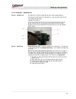
Setting:
Switch ON traction unit (Power ON), main switch lights up.
Set potentiometer LABEL SCANNER for optical label scanning to zero.
LED lamp on receiver (1) lights up. Move label gap (label web) right
underneath marking (3) of the receiver head (1). Turn potentiometer
LABEL SCANNER until LED lamp on receiver (1) goes off.
Please note figure on potentiometer scale.
Move label right underneath marking (3), the LED lamp on the receiver
head (1) lights up again.
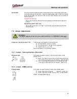
Example:
Setting of the potentiometer on label gap:
LED lamp switches off at 5,5
Setting of potentiometer on label:
LED switches off at 6
Therefore, the optimal setting of the potentiometer is at 5,75.
REMARKS!
The gap between two labels may not be recognized with
a bad adjustment of the optical label scanner! The labeler
will stop after 2000mm forward feeding (after start signal)
and the ERR-output will be set for a short time - if the
scanner does not see a gap! For transparent labels
(clear view) use a mechanical or capacitive label sensor
(fork sensor) – see below!
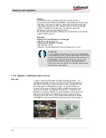
7.3.8 Adapter – alternative label sensors
Remarks
In case of clear few (transparent) labels and backing paper - the
standard optical label scanner is not able to scan the gap (between
two labels). Therefore an alternative sensor has to be used to work
with these types of labels/backing paper. Very good alternative
sensors for these type of labels could be mechanical sensors (see
right picture below) or a capacitive fork sensors – mounted on an
attachment unit. The attachment unit will be fixed to the modular rail
(see picture left below). The adjustment of these sensors is done
directly on the sensor itself – the potentiometer adjustment “LABEL
SCANNER” on the operator plate cannot be used for these sensors.
Mechanical- and optical sensor
Attachment unit „mechanical- or optical scanner“