5
Brake Pedal and Park Brake (Gas and Electric Vehicles)
ACCELERATOR AND BRAKE PEDAL GROUP
PARK BRAKE REMOVAL (GAS AND ELECTRIC VEHICLES)
1.
Disconnect the battery cables and either discharge the controller or disconnect the spark plug wire.
Disconnect the Batteries – Electric Vehicles, Section 1, Page 1-5.
See Disconnect the Battery- Gasoline Vehicles on page 1-4.
2.
Place chocks under the rear wheels and lift the front end of the vehicle with a chain hoist or floor jack. Place
jack stands under the front cross tube of the vehicle frame and lower the vehicle onto the jack stands.
See
following WARNING.
WARNING
• Lift only one end of the vehicle at a time. Use a suitable lifting device (chain hoist or hydraulic floor
jack) with 1000 lb (454 kg) minimum lifting capacity. Do not use lifting device to hold vehicle in raised
position. Use approved jack stands of proper weight capacity to support the vehicle and chock
the wheels that remain on the floor. When not performing a test or service procedure that requires
movement of the wheels, lock the brakes.
3.
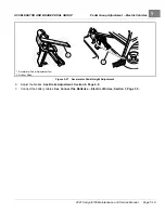
Remove the park brake assembly.
3.1.
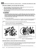
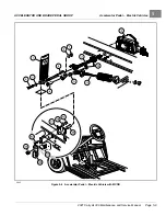
To remove the park brake rod and pawl assembly (17 through 20), remove the push nut (19) and disconnect
the ball joint sleeve (21) from the park brake pedal (1)
See following NOTE.
NOTE:
New push nuts (19) and (32) must be used when reassembling the park brake.
3.2.
To remove the park brake pedal (1), remove the push retainer nut (32), disconnect the torsion spring (22),
and slide the pedal off of the shaft.
See preceding NOTE.
3.3.
Inspect all parts for wear and damage and replace as necessary.
1
30
32
30
22
23
10
21
12
17
18
19
35
A
B
C
20
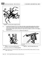
A. Hook one end of spring (20) on park brake weldment.
B. Lift other end of spring (20) up and over brake weldment by prying
down on shaft with small screwdriver.
C. Shaft
Figure 5-4
Park Brake Assembly
Figure 5-5
Torsion Spring Installation
PARK BRAKE INSTALLATION (GAS AND ELECTRIC VEHICLES)
1.
From the bottom side of the floorboard, insert the park brake rod (17) through the brake pedal assembly opening.
Then install the park brake pawl (35) onto the shaft on the brake pedal assembly (10) and also insert the park
brake rod (17) into the park brake pawl
.
2.
Install the push nut (19) on to the park brake pawl shaft.
3.
Install the spacer (23) and torsion spring (22) on the park brake pedal shaft on the brake pedal assembly.
Page 5-4
2021 Carryall 300 Maintenance and Service Manual
Содержание Carryall 300 2021
Страница 2: ......
Страница 16: ......
Страница 54: ...Pagination Page 4 Floor Mat BODY AND TRIM Page 4 20 2021 Carryall 300 Maintenance and Service Manual...
Страница 112: ...8 Tires WHEELS AND TIRES Figure 8 2 Inflate Tire Page 8 4 2021 Carryall 300 Maintenance and Service Manual...
Страница 118: ...Pagination Page 9 Jounce Bumpers REAR SUSPENSION Page 9 6 2021 Carryall 300 Maintenance and Service Manual...
Страница 406: ...Pagination Page 20 Snubber GASOLINE VEHICLE ENGINE Page 20 10 2021 Carryall 300 Maintenance and Service Manual...
Страница 454: ...Pagination Page 23 Driven Clutch GASOLINE VEHICLE CLUTCHES Page 23 20 2021 Carryall 300 Maintenance and Service Manual...
Страница 470: ...Pagination Page 24 Shifter Cable GASOLINE VEHICLE TRANSAXLE Page 24 16 2021 Carryall 300 Maintenance and Service Manual...
Страница 551: ...80 2018 by Kohler Co All rights reserved KohlerEngines com 17 690 15 Rev...
Страница 552: ...Pagination Page 25 Shifter Cable KOHLER ENGINE SERVICE MANUAL Page 25 2 2021 Carryall 300 Maintenance and Service Manual...
Страница 565: ...GASOLINE ENGINE HARNESS Wiring Diagrams Gasoline Engine Harness 26...
Страница 566: ...Page intentionally left blank...
Страница 567: ...GASOLINE KEY START MAIN HARNESS Wiring Diagrams Gasoline Key Start Main Harness 26...
Страница 568: ...Page intentionally left blank...
Страница 569: ...GASOLINE PEDAL START MAIN HARNESS Wiring Diagrams Gasoline Pedal Start Main Harness 26...
Страница 570: ...Page intentionally left blank...
Страница 571: ...GASOLINE INSTRUMENT PANEL HARNESS Wiring Diagrams Gasoline Instrument Panel Harness 26...
Страница 572: ...Page intentionally left blank...
Страница 573: ...GASOLINE FNR HARNESS Wiring Diagrams Gasoline FNR Harness 26...
Страница 574: ...Page intentionally left blank...
Страница 575: ...ELECTRIC MAIN HARNESS Wiring Diagrams Electric Main Harness 26...
Страница 576: ...Page intentionally left blank...
Страница 577: ...ELECTRIC INSTRUMENT PANEL HARNESS Wiring Diagrams Electric Instrument Panel Harness 26...
Страница 578: ...Page intentionally left blank...
Страница 579: ...ELECTRIC ACCESSORIES HARNESS Wiring Diagrams Electric Accessories Harness 26...
Страница 580: ...Page intentionally left blank...
Страница 588: ...NOTES...
Страница 589: ...NOTES...
Страница 590: ...NOTES...
Страница 591: ...NOTES...
Страница 592: ...NOTES...
Страница 593: ...NOTES...
Страница 594: ...NOTES...
Страница 595: ......
Страница 596: ......

