BODY AND TRIM
Tilt Bed
4
TILT BED REMOVAL
NOTE:
This procedure requires two people.
WARNING
• Remove all cargo before raising the bed or servicing the vehicle. If the vehicle is equipped with a prop
rod, ensure that it is securely engaged while bed is raised. Do not close bed until all persons are clear
of cargo bed area. Keep hands clear of all crush areas. Do not drop cargo bed; lower gently and keep
entire body clear. Failure to heed this warning could result in severe personal injury or death.
1.
Disconnect the batteries.
See Disconnect the Batteries – Electric Vehicles, Section 1, Page 1-5.
See Disconnect the Battery- Gasoline Vehicles on page 1-4.
2.
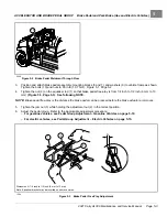
Raise bed. Hold bed securely in an upright position
3.
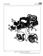
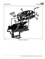
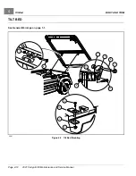
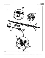
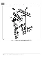
Remove locknut (7) from each hinge assembly. Lower bed onto vehicle frame.
4.
Apply slight upward pressure (by hand) on the rear of the bed to relieve pressure on the hinges, and remove the
hinge bolts (6) from the hinge assemblies.
See following WARNING and CAUTION.
WARNING
• Keep hands and arms from between the bed and vehicle frame and do not allow the bed to drop.
CAUTION
• Support bed as pins are removed.
• Keep bed and hinges aligned to avoid binding the pins during removal.
5.
Raise rear edge of bed approximately 6 inches (15.2 cm) and pull bed assembly toward rear of vehicle
approximately 3 inches (7.6 cm) to release bed latch assembly from latch plate (12).
6.
Lift bed from vehicle.
TILT BED INSTALLATION
NOTE:
This procedure requires two people.
Lubricate the hinge bolts (6) with light motor oil prior to assembly.
1.
Hold bed at a slight angle (front of bed lower than rear of bed) to vehicle and place front edge of bed onto vehicle
frame. Bed latches should engage with latch plates (12)
.
2.
Lower edge of bed onto vehicle and align hinge brackets (9) with bed hinge.
See following WARNING and
CAUTION.
WARNING
• Keep hands and arms from between the bed and vehicle frame and do not allow the bed to drop.
CAUTION
• Keep bed and hinges aligned to avoid binding the pins during installation.
3.
Start the bolts (6) into left and right hinge assemblies. It may be necessary to use an alignment tool to align holes
in hinge bracket with steel bushing in hinge assembly.
2021 Carryall 300 Maintenance and Service Manual
Page 4-13
Содержание Carryall 300 2021
Страница 2: ......
Страница 16: ......
Страница 54: ...Pagination Page 4 Floor Mat BODY AND TRIM Page 4 20 2021 Carryall 300 Maintenance and Service Manual...
Страница 112: ...8 Tires WHEELS AND TIRES Figure 8 2 Inflate Tire Page 8 4 2021 Carryall 300 Maintenance and Service Manual...
Страница 118: ...Pagination Page 9 Jounce Bumpers REAR SUSPENSION Page 9 6 2021 Carryall 300 Maintenance and Service Manual...
Страница 406: ...Pagination Page 20 Snubber GASOLINE VEHICLE ENGINE Page 20 10 2021 Carryall 300 Maintenance and Service Manual...
Страница 454: ...Pagination Page 23 Driven Clutch GASOLINE VEHICLE CLUTCHES Page 23 20 2021 Carryall 300 Maintenance and Service Manual...
Страница 470: ...Pagination Page 24 Shifter Cable GASOLINE VEHICLE TRANSAXLE Page 24 16 2021 Carryall 300 Maintenance and Service Manual...
Страница 551: ...80 2018 by Kohler Co All rights reserved KohlerEngines com 17 690 15 Rev...
Страница 552: ...Pagination Page 25 Shifter Cable KOHLER ENGINE SERVICE MANUAL Page 25 2 2021 Carryall 300 Maintenance and Service Manual...
Страница 565: ...GASOLINE ENGINE HARNESS Wiring Diagrams Gasoline Engine Harness 26...
Страница 566: ...Page intentionally left blank...
Страница 567: ...GASOLINE KEY START MAIN HARNESS Wiring Diagrams Gasoline Key Start Main Harness 26...
Страница 568: ...Page intentionally left blank...
Страница 569: ...GASOLINE PEDAL START MAIN HARNESS Wiring Diagrams Gasoline Pedal Start Main Harness 26...
Страница 570: ...Page intentionally left blank...
Страница 571: ...GASOLINE INSTRUMENT PANEL HARNESS Wiring Diagrams Gasoline Instrument Panel Harness 26...
Страница 572: ...Page intentionally left blank...
Страница 573: ...GASOLINE FNR HARNESS Wiring Diagrams Gasoline FNR Harness 26...
Страница 574: ...Page intentionally left blank...
Страница 575: ...ELECTRIC MAIN HARNESS Wiring Diagrams Electric Main Harness 26...
Страница 576: ...Page intentionally left blank...
Страница 577: ...ELECTRIC INSTRUMENT PANEL HARNESS Wiring Diagrams Electric Instrument Panel Harness 26...
Страница 578: ...Page intentionally left blank...
Страница 579: ...ELECTRIC ACCESSORIES HARNESS Wiring Diagrams Electric Accessories Harness 26...
Страница 580: ...Page intentionally left blank...
Страница 588: ...NOTES...
Страница 589: ...NOTES...
Страница 590: ...NOTES...
Страница 591: ...NOTES...
Страница 592: ...NOTES...
Страница 593: ...NOTES...
Страница 594: ...NOTES...
Страница 595: ......
Страница 596: ......


