ELECTRIC VEHICLE - ELECTRICAL SYSTEM
TROUBLESHOOTING
Troubleshooting
12
TROUBLESHOOTING
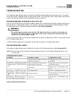
The following troubleshooting guides will be helpful in identifying operating difficulties should they occur. The guides
include the symptom, probable cause(s) and suggested checks. The procedures used for making these checks can be
found in the referenced sections of this maintenance and service manual.
TROUBLESHOOTING THE VEHICLE WITH THE CDT
Club Car recommends the use of the CDT handheld programmer for troubleshooting vehicles equipped with the Excel
electrical system. Troubleshooting Guide 1 is to be used in conjunction with the CDT handheld programmer.
See
Controller Diagnostic Tool (CDT)
for operating instructions.
See following WARNING.
WARNING
• The vehicle operator should not monitor the CDT while the vehicle is in motion. A technician can
monitor the CDT while traveling as a passenger in the vehicle. Failure to heed this warning could
result in severe personal injury or death.
In the event that the vehicle is not functioning properly after completing Troubleshooting Guide 1, the technician should
go to Troubleshooting Guide 2.
If a CDT handheld programmer is unavailable, the technician should go to Troubleshooting Guide 2.
TROUBLESHOOTING GUIDE 1
The following troubleshooting guide is intended for use with a CDT handheld programmer.
See following NOTE.
NOTE:
Before troubleshooting the vehicle, check the diagnostic history from the Special Diagnostics Menu. Note
any fault codes.
_
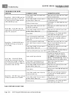
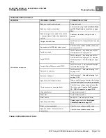
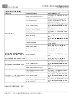
TROUBLESHOOTING GUIDE 1
SYMPTOM
POSSIBLE CAUSES
CORRECTIVE ACTION
Loose or disconnected three-pin connector at
the MCOR or broken wire
Repair and/or connect the three-pin connector
to the MCOR
Loose or disconnected 16-pin connector at
speed controller or broken wire
Repair and/or connect the 16-pin connector
to the speed controller
Monitor Menu – THROTTLE % value does not
increase as the accelerator pedal is pressed
or Diagnostic Menu – THROTTLE FAULT fault
code
Failed MCOR
Test Procedure 11 – MCOR Voltage on page
Over-adjusted brakes
Section 6 – Wheel Brake Assemblies
Monitor Menu – TEMPERATURE °C indicates
that temperature is above 85 °C (145 °F) or
Diagnostic Menu – THERMAL CUTBACK fault
code
Vehicle is overloaded
Ensure that vehicle is not overloaded before
returning to operation
Monitor Menu – ARM PWM value does not
reach 100% when vehicle is at full speed
Failed MCOR
Test Procedure 11 – MCOR Voltage on page
TABLE CONTINUED ON NEXT PAGE
2021 Carryall 300 Maintenance and Service Manual
Page 12-5
Содержание Carryall 300 2021
Страница 2: ......
Страница 16: ......
Страница 54: ...Pagination Page 4 Floor Mat BODY AND TRIM Page 4 20 2021 Carryall 300 Maintenance and Service Manual...
Страница 112: ...8 Tires WHEELS AND TIRES Figure 8 2 Inflate Tire Page 8 4 2021 Carryall 300 Maintenance and Service Manual...
Страница 118: ...Pagination Page 9 Jounce Bumpers REAR SUSPENSION Page 9 6 2021 Carryall 300 Maintenance and Service Manual...
Страница 406: ...Pagination Page 20 Snubber GASOLINE VEHICLE ENGINE Page 20 10 2021 Carryall 300 Maintenance and Service Manual...
Страница 454: ...Pagination Page 23 Driven Clutch GASOLINE VEHICLE CLUTCHES Page 23 20 2021 Carryall 300 Maintenance and Service Manual...
Страница 470: ...Pagination Page 24 Shifter Cable GASOLINE VEHICLE TRANSAXLE Page 24 16 2021 Carryall 300 Maintenance and Service Manual...
Страница 551: ...80 2018 by Kohler Co All rights reserved KohlerEngines com 17 690 15 Rev...
Страница 552: ...Pagination Page 25 Shifter Cable KOHLER ENGINE SERVICE MANUAL Page 25 2 2021 Carryall 300 Maintenance and Service Manual...
Страница 565: ...GASOLINE ENGINE HARNESS Wiring Diagrams Gasoline Engine Harness 26...
Страница 566: ...Page intentionally left blank...
Страница 567: ...GASOLINE KEY START MAIN HARNESS Wiring Diagrams Gasoline Key Start Main Harness 26...
Страница 568: ...Page intentionally left blank...
Страница 569: ...GASOLINE PEDAL START MAIN HARNESS Wiring Diagrams Gasoline Pedal Start Main Harness 26...
Страница 570: ...Page intentionally left blank...
Страница 571: ...GASOLINE INSTRUMENT PANEL HARNESS Wiring Diagrams Gasoline Instrument Panel Harness 26...
Страница 572: ...Page intentionally left blank...
Страница 573: ...GASOLINE FNR HARNESS Wiring Diagrams Gasoline FNR Harness 26...
Страница 574: ...Page intentionally left blank...
Страница 575: ...ELECTRIC MAIN HARNESS Wiring Diagrams Electric Main Harness 26...
Страница 576: ...Page intentionally left blank...
Страница 577: ...ELECTRIC INSTRUMENT PANEL HARNESS Wiring Diagrams Electric Instrument Panel Harness 26...
Страница 578: ...Page intentionally left blank...
Страница 579: ...ELECTRIC ACCESSORIES HARNESS Wiring Diagrams Electric Accessories Harness 26...
Страница 580: ...Page intentionally left blank...
Страница 588: ...NOTES...
Страница 589: ...NOTES...
Страница 590: ...NOTES...
Страница 591: ...NOTES...
Страница 592: ...NOTES...
Страница 593: ...NOTES...
Страница 594: ...NOTES...
Страница 595: ......
Страница 596: ......

