


16
Motor Component Testing and Inspection
ELECTRIC VEHICLE - MOTOR
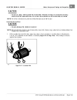
MOTOR FRAME AND FIELD WINDINGS INSPECTION
1.
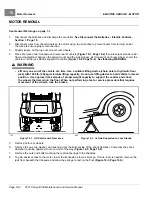
Remove the motor from the vehicle.
See Motor Removal on page 16-4.
2.
Remove the and cap and armature by performing steps 1 through 7 of Motor Disassembly on page 16-6.
3.
Burned or scorched insulation on the field windings indicates the motor has overheated due to overloads or
grounded or shorted coil windings. If the insulation on the field windings is scorched, replace the motor or
the stator shell assembly.
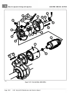
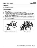
MOTOR BRUSH, SPRING, AND TERMINAL INSULATOR INSPECTION
Brush Spring Tension Test
1.
Remove the motor from the vehicle.
See Motor Removal on page 16-4.
2.
Remove the end cap and armature by performing steps 1 through 7 of Motor Disassembly on page 16-6.
3.
Inspect the brush springs (14)
. Replace springs that are discolored from heat
(light gold or blue tinted).
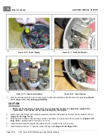
4.
Test the brush springs for proper tension.
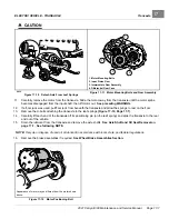
4.1.
Place a C-shaped steel plate on a scale.
4.2.
Place the end of the C-shaped plate so that it is between the spring and the brush as shown
.
4.3.
Gently pull the scale to obtain the spring tension reading.
See following CAUTION.
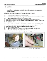
CAUTION
• When checking brush spring tension, do not over-extend the spring. Using excessive force will
damage the spring.
4.4.
Replace springs which require a force of less than 35 ozf (0.99 kgf)
.
See
following NOTE.
NOTE:
When installing new brushes, remove and replace brushes one at a time. This method ensures the terminals
and brushes will be properly positioned in the rigging. Refer to
for brush
installation.
When replacing brushes, replace all four brushes. Never replace only two.
Install the brushes in the same rigging 180° apart from each other.
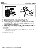
Brush Inspection
1.
Remove the motor from the vehicle.
See Motor Removal on page 16-4.
2.
Remove the end cap and armature by performing steps 1 through 7 of Motor Disassembly on page 16-6.
3.
Inspect the brushes (13) for damage or excessive wear
. Replace brushes if required.
See preceding NOTE.
4.
Use dial calipers or a micrometer to measure the brush length. The minimum-allowable brush length is 0.62
inches (16 mm). Replace the set of brushes as required.
See preceding NOTE.
Terminal Insulator Inspection
1.
Remove the motor from the vehicle.
See Motor Removal on page 16-4.
2.
Remove the terminal insulators by performing steps 1 through 12 of Motor Disassembly on page 16-6.
3.
Inspect the insulators (4 and 6) for cracks or other damage
. Replace insulators
as required.
Page 16-10
2021 Carryall 300 Maintenance and Service Manual
Содержание Carryall 300 2021
Страница 2: ......
Страница 16: ......
Страница 54: ...Pagination Page 4 Floor Mat BODY AND TRIM Page 4 20 2021 Carryall 300 Maintenance and Service Manual...
Страница 112: ...8 Tires WHEELS AND TIRES Figure 8 2 Inflate Tire Page 8 4 2021 Carryall 300 Maintenance and Service Manual...
Страница 118: ...Pagination Page 9 Jounce Bumpers REAR SUSPENSION Page 9 6 2021 Carryall 300 Maintenance and Service Manual...
Страница 406: ...Pagination Page 20 Snubber GASOLINE VEHICLE ENGINE Page 20 10 2021 Carryall 300 Maintenance and Service Manual...
Страница 454: ...Pagination Page 23 Driven Clutch GASOLINE VEHICLE CLUTCHES Page 23 20 2021 Carryall 300 Maintenance and Service Manual...
Страница 470: ...Pagination Page 24 Shifter Cable GASOLINE VEHICLE TRANSAXLE Page 24 16 2021 Carryall 300 Maintenance and Service Manual...
Страница 551: ...80 2018 by Kohler Co All rights reserved KohlerEngines com 17 690 15 Rev...
Страница 552: ...Pagination Page 25 Shifter Cable KOHLER ENGINE SERVICE MANUAL Page 25 2 2021 Carryall 300 Maintenance and Service Manual...
Страница 565: ...GASOLINE ENGINE HARNESS Wiring Diagrams Gasoline Engine Harness 26...
Страница 566: ...Page intentionally left blank...
Страница 567: ...GASOLINE KEY START MAIN HARNESS Wiring Diagrams Gasoline Key Start Main Harness 26...
Страница 568: ...Page intentionally left blank...
Страница 569: ...GASOLINE PEDAL START MAIN HARNESS Wiring Diagrams Gasoline Pedal Start Main Harness 26...
Страница 570: ...Page intentionally left blank...
Страница 571: ...GASOLINE INSTRUMENT PANEL HARNESS Wiring Diagrams Gasoline Instrument Panel Harness 26...
Страница 572: ...Page intentionally left blank...
Страница 573: ...GASOLINE FNR HARNESS Wiring Diagrams Gasoline FNR Harness 26...
Страница 574: ...Page intentionally left blank...
Страница 575: ...ELECTRIC MAIN HARNESS Wiring Diagrams Electric Main Harness 26...
Страница 576: ...Page intentionally left blank...
Страница 577: ...ELECTRIC INSTRUMENT PANEL HARNESS Wiring Diagrams Electric Instrument Panel Harness 26...
Страница 578: ...Page intentionally left blank...
Страница 579: ...ELECTRIC ACCESSORIES HARNESS Wiring Diagrams Electric Accessories Harness 26...
Страница 580: ...Page intentionally left blank...
Страница 588: ...NOTES...
Страница 589: ...NOTES...
Страница 590: ...NOTES...
Страница 591: ...NOTES...
Страница 592: ...NOTES...
Страница 593: ...NOTES...
Страница 594: ...NOTES...
Страница 595: ......
Страница 596: ......


