


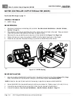


ELECTRIC VEHICLE - ELECTRICAL SYSTEM
TROUBLESHOOTING
Test Procedures
12
1.
If necessary, see Testing Basics on page 12-12.
2.
Disconnect the batteries and discharge the controller.
See Disconnect the Batteries – Electric Vehicles
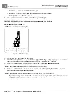
3.
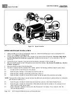
Remove the instrument panel.
See Instrument Panel Removal, Section 4, Page 4-9.
4.
Disconnect the orange/white and pink wires from the reverse buzzer.
5.
Place the Run/Tow switch in the TOW position and connect the batteries.
See Connect the Batteries – Electric
6.
Place the key switch in the OFF position and the Run/Tow switch in the RUN position.
7.
Using a multimeter set to 200 volts DC, place the black (–) probe on battery no. 6 (6 x 8-Volt battery set) negative
post and place the red (+) probe on the pink wire terminal end that was disconnected from the reverse buzzer.
The reading should be approximately 48 volts (full battery voltage).
7.1.
If the voltage reading is correct, go to step 7.
7.2.
If reading is zero volts, check wire continuity, 9-pin connector, 15-amp fuse and Run/Tow switch.
See Test
Procedure 3 – Run/Tow Switch on page 12-15.
7.3.
If the continuity readings are not correct, repair or replace the pink wire.
7.4.
If the continuity readings are correct, go to step 7.
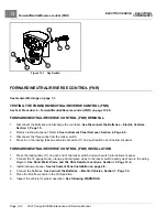
8.
Place the Forward/Neutral/Reverse control (FNR) in REVERSE. Using a multimeter set to 200 volts DC, place the
black (–) probe on the orange/white wire terminal end (that was disconnected from the reverse buzzer) and place
the red (+) probe on battery no. 1 positive post. The reading should be approximately 48 volts (full battery voltage).
8.1.
If the voltage reading is correct, replace the reverse buzzer.
8.2.
If reading is zero volts, check orange/white wire continuity and connection at Pin 7 in 16-Pin connector.
8.3.
If there is no continuity in the orange/white wire, or the pin 7 terminal in the 16-pin connector is not properly
seated, repair or replace as required.
8.4.
If the orange/white wire continuity and 16-Pin connector are correct and there is no voltage at the orange
wire, replace the controller.
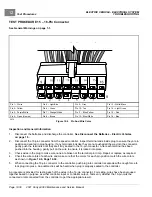
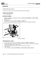
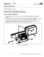
TEST PROCEDURE 17 – Charge Indicator Light
See General Warnings on page 1-1.
1.
With batteries connected, Run/Tow switch in the RUN position and the key switch in the OFF position, connect
charger DC cord to vehicle.
2.
In a few seconds, the light will flash three times and the reverse buzzer simultaneously will sound three times to
indicate charging has begun.
See following NOTE.
NOTE:
The number of flashes and beeps can vary depending on the Beep Option setting.
3.
If charge indicator light does not flash three times, disconnect charger DC cord from vehicle and connect a
CDT to the vehicle.
4.
Access the Monitor menu and select LED Driver by using the SCROLL DISPLAY buttons. The CDT should
indicate OFF.
5.
Reconnect charger DC cord to vehicle.
6.
In a few seconds, the CDT should quickly display ON just once while the dash-mounted charge indicator light
flashes three times.
See following NOTE.
NOTE:
The CDT will still flash ON even with a failed or missing charge indicator light.
7.
If the CDT quickly displays ON but the charge indicator light still does not flash, check the following items:
– Condition of the blue/yellow wire terminal in the 16-pin connector.
2021 Carryall 300 Maintenance and Service Manual
Page 12-33
Содержание Carryall 300 2021
Страница 2: ......
Страница 16: ......
Страница 54: ...Pagination Page 4 Floor Mat BODY AND TRIM Page 4 20 2021 Carryall 300 Maintenance and Service Manual...
Страница 112: ...8 Tires WHEELS AND TIRES Figure 8 2 Inflate Tire Page 8 4 2021 Carryall 300 Maintenance and Service Manual...
Страница 118: ...Pagination Page 9 Jounce Bumpers REAR SUSPENSION Page 9 6 2021 Carryall 300 Maintenance and Service Manual...
Страница 406: ...Pagination Page 20 Snubber GASOLINE VEHICLE ENGINE Page 20 10 2021 Carryall 300 Maintenance and Service Manual...
Страница 454: ...Pagination Page 23 Driven Clutch GASOLINE VEHICLE CLUTCHES Page 23 20 2021 Carryall 300 Maintenance and Service Manual...
Страница 470: ...Pagination Page 24 Shifter Cable GASOLINE VEHICLE TRANSAXLE Page 24 16 2021 Carryall 300 Maintenance and Service Manual...
Страница 551: ...80 2018 by Kohler Co All rights reserved KohlerEngines com 17 690 15 Rev...
Страница 552: ...Pagination Page 25 Shifter Cable KOHLER ENGINE SERVICE MANUAL Page 25 2 2021 Carryall 300 Maintenance and Service Manual...
Страница 565: ...GASOLINE ENGINE HARNESS Wiring Diagrams Gasoline Engine Harness 26...
Страница 566: ...Page intentionally left blank...
Страница 567: ...GASOLINE KEY START MAIN HARNESS Wiring Diagrams Gasoline Key Start Main Harness 26...
Страница 568: ...Page intentionally left blank...
Страница 569: ...GASOLINE PEDAL START MAIN HARNESS Wiring Diagrams Gasoline Pedal Start Main Harness 26...
Страница 570: ...Page intentionally left blank...
Страница 571: ...GASOLINE INSTRUMENT PANEL HARNESS Wiring Diagrams Gasoline Instrument Panel Harness 26...
Страница 572: ...Page intentionally left blank...
Страница 573: ...GASOLINE FNR HARNESS Wiring Diagrams Gasoline FNR Harness 26...
Страница 574: ...Page intentionally left blank...
Страница 575: ...ELECTRIC MAIN HARNESS Wiring Diagrams Electric Main Harness 26...
Страница 576: ...Page intentionally left blank...
Страница 577: ...ELECTRIC INSTRUMENT PANEL HARNESS Wiring Diagrams Electric Instrument Panel Harness 26...
Страница 578: ...Page intentionally left blank...
Страница 579: ...ELECTRIC ACCESSORIES HARNESS Wiring Diagrams Electric Accessories Harness 26...
Страница 580: ...Page intentionally left blank...
Страница 588: ...NOTES...
Страница 589: ...NOTES...
Страница 590: ...NOTES...
Страница 591: ...NOTES...
Страница 592: ...NOTES...
Страница 593: ...NOTES...
Страница 594: ...NOTES...
Страница 595: ......
Страница 596: ......


