background image


CTD-N Technical Manual 

P/N 95F-6000-00 (February 2017)   

page 73 

EAR-Controlled Technology Subject to Restrictions Contained on the Cover Page.


Do NOT use high pressure or you may damage softer surfaces. 
Always dry the system before placing it in the storage case to avoid fungus or mold growth. 


After cleaning the instrument, check it carefully for signs of damage. Check the bulkhead connector 

for looseness or other signs of damage. Check the pins of the bulkhead connector. They should be 

kept clean at all times. Clean the connector pins and sockets with an alcohol wipe, and when recon-

necting, lubricate the rubber portion of the pins with an O-ring quality silicone based lubricant. If 

one or more optional sensors are installed, the end cap includes, in addition to the 6-pin bulkhead 

connector, an Options 1 and Options 2 connector. For information on these connectors and the op-

tional sensors, refer to 

APPENDIX C: Optional Sensors

.  


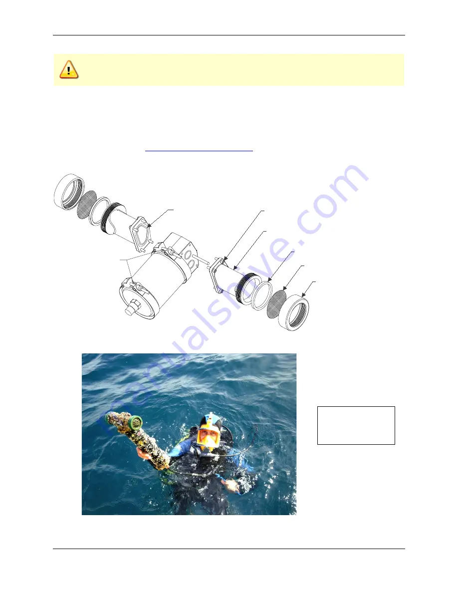
Figure 42. 

Cleaning the CTD-NH Sensor Head 


Photo by OceanNetConsulting, Spain 

2-131 O-Ring

Copper Screen

Collar

Screen Collar

Intake Fitting

8-32 Screw/Lock Washer/Flat Washer

Locking Clamps

Notice how there is 

no marine growth on 

the copper screens. 

Содержание CT-NH

Страница 1: ...exception or other approval from the appropriate U S Government agency before being exported from the United States or provided to any foreign person Diversion contrary to U S law is prohibited CTD N...

Страница 2: ...EAR Controlled Technology Subject to Restrictions Contained on the Cover Page...

Страница 3: ...Baud Rate of the Serial Port 19 Automatically Changing the Baud Rate of the Serial Port to the Baud Rate of the CTD N 20 Changing the Baud Rate of the CTD N and the Serial Port 20 Connecting and Setti...

Страница 4: ...ce 71 Cleaning and Inspecting the CTD N 72 Replacing the Battery Pack 74 Oil Fill Procedure and Capillary Tube Installation 78 Installing a CTD N End Cap Switch Kit 81 Firmware Updates 82 APPENDIX A M...

Страница 5: ...hipments 157 European Shipments 158 List of Figures Figure 1 The Location of the CTD NV Main External Components 4 Figure 2 The Location of the CTD NH Main External Components 5 Figure 3 The Location...

Страница 6: ...for Image Files 63 Figure 36 The File Information Window 64 Figure 37 The Channel Configuration Dialog Box 67 Figure 38 The CTD N Acquisition Window 68 Figure 39 The Acquisition Setup Dialog Box 68 F...

Страница 7: ...pdated cleaning procedure Updated Oil Fill Procedure and Capillary Tube Assembly Updated TRDI website address to http www teledynemarine com rdi April 2016 Updated Internal Memory specification from 1...

Страница 8: ...only COM port 1 is supported Added note that Windows 7 will not save any data files to the folder selected in the dia log box Instead it saves to the desktop by default November 2011 Updated outline...

Страница 9: ...n and others The RS 232 channel interfaces with many external sensors via an RS 232 se rial connection Two of the DC channels include two logic outputs for controlling sensor gains or other sensor fun...

Страница 10: ...recommended 50 MB Free Disk Space plus space for data files A large fast hard disk is recommended One Serial Port two or more High Speed UART Serial Port recommended Minimum display resolution of 1024...

Страница 11: ...chnical support call 1 858 842 2700 Self Service Customer Portal Use our online customer portal at http www teledynemarine com rdi and click on the Support link to down load manuals firmware updates s...

Страница 12: ...ressure through a pressure port and an oil filled capillary The oil provides the required pressure coupling and is an electrical insulator that prevents corrosion due to the dissimilar metal compositi...

Страница 13: ...ect to Restrictions Contained on the Cover Page Figure 2 The Location of the CTD NH Main External Components NOTE Shown with optional wire bail and with the oil capillary tube installed The tube exten...

Страница 14: ...ctions Contained on the Cover Page Figure 3 The Location of the CT NH Main External Components NOTE Shown with optional wire bail 3 16 Wire Bail Shown With Optional External Sensor Interface Connector...

Страница 15: ...ion 2 connectors are used to connect to op tional external sensors See APPENDIX C Optional Sensors for more information Battery Pack An internal alkaline battery pack is used to power the CTD N when t...

Страница 16: ...nium housing Sample rate 1 15 S sec selectable Resolution 20 bits Bulkhead connector Subconn MCBH4F mates with MCIL4M Direct Reading unit Subconn MCBH6F mates with MCIL6M Battery powered and Ex ternal...

Страница 17: ...0001 mS cm 1 Specified at 22 C and 35PSU Defined as the root sum of the squares RSS of endpoint non linearity repeatability error and calibration uncertainty 2 Specified from 0 70 mS cm 3 Over 1 year...

Страница 18: ...D N Technical Manual page 10 EAR Controlled Technology Subject to Restrictions Contained on the Cover Page Outline Installation Drawings Figure 4 Outline Installation Drawing CTD NV CT NV NXIC Vertica...

Страница 19: ...ANGLES DRILLED HOLES DECIMALS TOLERANCES CHECKED RELEASED DRAWN P WALTERS e 63 NONE SCALE SHEET 1 SIZE DWG NO OF 1 REV CAGE CODE APPROVED OVERALL LENGTH HOUSING LENGTH EXTERNAL SENSOR INTERFACE DIREC...

Страница 20: ...ument communi cate Unpacking the CTD N Before unpacking the CTD N check the shipping container for signs of external damage If the con tainer appears damaged report the damage to TRDI and to the freig...

Страница 21: ...tact TRDI to order any of these items Table 1 Optional Items Available from TRDI ITEM TRDI PART NUMBER Test Cable NXIC OP CAB PWR RS 485 RS 232 Converter 3201 RS232 485 Alkaline Battery Pack B176 030...

Страница 22: ...the CTDPro Main window Figure 6 The Properties Dialog Box Communication Interfaces The CTD N includes three communications interfaces for configuring and downloading data from the instrument The inst...

Страница 23: ...rt on the computer NOTE If you will be fabricating your own cable for connecting the CTD N to your computer see APPENDIX B Bulkhead Connector Wiring for information on the CTD N bulkhead connector com...

Страница 24: ...NOTE The battery must always be removed whenever the unit is being shipped or stored for long periods The CTD N End Cap Switch disconnects the battery without the need to open the unit A special 6 pi...

Страница 25: ...ect the test cable to the bulkhead connector on the instrument and to the RS 485 con nector of the RS 485 RS 232 converter For those customers who order an RS485 RS232 converter from us we ship a B B...

Страница 26: ...puters only COM port 1 is supported To change the serial port 1 Choose Start All Programs RD Instruments CTDPro CTDPro starts and the CTDPro Main window opens 2 Choose CTD Communications Setup The Com...

Страница 27: ...automatically determines the baud rate of the instrument and then changes the baud rate of the computer s serial port to the same The baud rate of the instrument is not changed This allows communicati...

Страница 28: ...e instrument and then changes the baud rate of the serial port to the same When changed the Found CTD N window opens confirming the se rial port to which the instrument is connected and the selected b...

Страница 29: ...connect it to your computer With the GPS connected you can have CTDPro include the latitude longitude and time of day with the data A NEMA GPGGA string is required To connect a GPS connect the RS 232...

Страница 30: ...e serial port to which the GPS is connected from the Communication Port drop down list box 4 Select the baud rate for the serial port from the Baudrate drop down list box The default baud rate is 4800...

Страница 31: ...the data output format NOTE Before you can configure the CTD N you must select it in CTDPro as described in Selecting the CTD N The CTD menu will not be displayed unless the CTD N is selected CTD N C...

Страница 32: ...mode but where the instru ment begins acquiring and storing data at a future date and time the Start Date and Start Time This mode allows the instrument to be set up on shore after which data are not...

Страница 33: ...he Record Time can be averaged over a specified interval the Average Time The Average Time is entered in minutes and seconds in the Length scroll box which is in the Average Time area of the CTD N Con...

Страница 34: ...The CTD N time and date are displayed in the CTD Time and CTD Date displays in the CTD N Con figuration dialog box The time and date can be reset at any time to that of the computer on which CTDPro i...

Страница 35: ...and close the Advanced Setting dialog box The hardware functions that can be modified are the following Output Data on Power Up causes the instrument to immediately output data when power is applied...

Страница 36: ...period and that there is enough memory to store all the data acquired during this period CTDPro provides an estimator which calculates the available running days based on the selected running mode an...

Страница 37: ...automatically CAUTION Do not enter the measured current drawn from an external power supply in the CTD Current text box The entry in the CTD Current text box is the average current drawn from an insta...

Страница 38: ...and then enter the Interval Time and Record Time Select Delayed Continuous click Next and then enter the Start Date and Start Time Select Delayed Interval click Next and then enter the Interval Time t...

Страница 39: ...drop down list box and select the folder in which to save the battery pack information file 14 In the File name text box enter the name of the file in which to save the battery pack infor mation The...

Страница 40: ...n the CTD N and verify calibration of the CTD N conductivity sensor 1 Connect the CTD N to your computer 2 Choose Start All Programs RD Instruments CTDPro CTDPro starts and the CTDPro Main window open...

Страница 41: ...As dialog box for diagnostics data files closes CTDPro performs diagnostic testing of the CTD N and the results are displayed as check marks in the appropriate Pass and Fail check boxes in the A D Rea...

Страница 42: ...r Page Figure 21 Save As Dialog Box for Diagnostics Data Files Figure 22 Results of Diagnostic Testing in the Diagnostics Dialog Box After diagnostic testing is complete the diagnostics data is saved...

Страница 43: ...ed on the Cover Page 8 Note The Loop Test was partially implemented for long term stability testing of CTDs for factory use it is not intended as a verification of calibration and should not be used a...

Страница 44: ...pack will not affect the instrument s configuration stored data or time and date settings 2 Connect the CTD N to your computer 3 Choose Start All Programs RD Instruments CTDPro CTDPro starts and the...

Страница 45: ...and down arrows in the Length scroll box to enter the Average Time in minutes and seconds mm ss 11 Click Deploy The Erase Memory window opens NOTE Clicking No in the Erase Memory window will append th...

Страница 46: ...stall the dummy plug will cause the connector pins to corrode and may cause damage to the instrument 17 Deploy the instrument in the required manner Configuring and Deploying the CTD N in Interval Mod...

Страница 47: ...at of the computer and the instrument Click OK to save the new time and date and close the Set Time window 7 In the Running Mode area of the CTD N Configuration dialog box select Interval 8 Using the...

Страница 48: ...click Erase A CTDPro window opens asking if you want to erase all of memory 13 Click Yes to confirm that you want to erase all of memory The memory is erased as indicated by the Erase Status progress...

Страница 49: ...ploy the instrument in the required manner Configuring and Deploying the CTD N in Delayed Start Continuous Mode To configure a CTD N for deployment and to acquire and store data in Delayed Start Conti...

Страница 50: ...select Delayed Start Con tinuous 8 Enter the Start Date in months days and years mm dd yyyy in the Start Date scroll box by clicking the month day and year digits one at a time and then entering the i...

Страница 51: ...lick Erase A CTD N window opens asking if you want to erase all of memory 14 Click Yes to confirm that you want to erase all of memory The memory is erased as indicated by the Erase Status progress ba...

Страница 52: ...ed manner Configuring and Deploying the CTD N in Delayed Start Interval Mode To configure a CTD N for deployment and to acquire and store data in Delayed Start Interval mode 1 If necessary replace the...

Страница 53: ...yyyy in the Start Date scroll box by clicking the month day and year digits one at a time and then entering the information directly Or instead click the down arrow to open a calendar Click the left o...

Страница 54: ...e Erase Memory window opens NOTE Clicking No in the Erase Memory window will append the new data file to the last data file stored in memory No memory will be erased 14 To erase all of memory click Er...

Страница 55: ...rting plug will cause the CTD N to open a file and start taking interval data immediately The files will be automatically sequentially named starting with INT01 Once the deployment is completed the ba...

Страница 56: ...behavior can be viewed in the termi nal window which can be opened by following the menu path view terminal When the instrument senses that it is in water above the conductivity threshold for 30 secon...

Страница 57: ...advisable to wait a couple of minutes to ensure that the file closes Similarly wait more than 30 seconds before redeployment or else a new file will not be created and logging will continue on the sa...

Страница 58: ...ormer method is required Autolog Typical Applications and Procedures Several applications are discussed here with the steps necessary to properly use the Autolog fea ture Using the Autolog feature wit...

Страница 59: ...r the instrument 16 Recover the instrument i e pull it out of the water 17 After 30 seconds out of the water the instrument will automatically stop logging to the file save the file and close the file...

Страница 60: ...is time is short then the end cap switch isn t greatly missed Secondly the user must ensure that the instrument is commanded into run mode using CTDPro s terminal window as cycling the power is not an...

Страница 61: ...data In addition when exporting data to a text or spreadsheet file or to CTDPost you can choose to have CTDPro calculate additional parameters from the measured parameters as described in Exporting Sa...

Страница 62: ...re 25 opens Figure 25 The Download Dialog Box 5 Click the file you want to download and then click Download The Save As dialog box for CTD data files shown in Figure 26 opens This dialog box is used t...

Страница 63: ...Download dialog box to close it Exporting and Viewing Saved Data After data have been downloaded from the CTD N and saved to a CTD data file the data in the CTD file can be exported to a text file a f...

Страница 64: ...heck boxes for the data that you want to export Clear the check boxes for the data that you do not NOTE Parameters in the Channels area of the Export dialog box are measured or calculated by the CTD N...

Страница 65: ...are exported to a file of the same file name and placed in the same directory as the original data file The appropriate extension is also added to the file name depending on whether it is a text file...

Страница 66: ...have been downloaded from the CTD N and saved to a CTD data file the data in the CTD file can viewed on graphs in a graphics display and the graphs can be printed and saved CTDPro provides graphs of...

Страница 67: ...lect time for the horizontal axis select the vs Time op tion in the Plot Type area of the Properties dialog to select pressure select the vs Pressure option Viewing Data on a Graph To view data on a g...

Страница 68: ...ected graph is displayed in the graphics display as shown Figure 32 for the tempera ture data and in Figure 33 for the pressure data Zooming in and Out of a Graph To zoom in on a graph press and hold...

Страница 69: ...Controlled Technology Subject to Restrictions Contained on the Cover Page Properties dialog box For complete instructions on how to set up the graph click Help in the dialog box Figure 31 The 2D Char...

Страница 70: ...The Pressure Graph Saving a Graph Graphs can be saved as JPG files files of extension jpg and opened in any photo editor To save a graph 1 View the graph as described in Viewing Data on a Graph 2 Cho...

Страница 71: ...he Quality text box in the Save Graph dialog box The higher the number the higher the quality and the larger the file size 8 If a grayscale image is desired select the Grayscale check box 9 To compres...

Страница 72: ...the Data Files All the data files that stored in the CTD N can be erased if the instrument is not logging data To erase all the data files in the CTD N 1 Connect the CTD N to your computer 2 Choose S...

Страница 73: ...ined on the Cover Page 5 Click Yes to erase all of memory A CTDPro window opens asking if you want to erase all of memory 6 Click Yes to confirm that you want to erase all of memory The memory is eras...

Страница 74: ...mputer The data are saved to a DAT file a file of extension dat which is in ASCII format and can be opened and viewed in any text editor NOTE Before deploying the CTD N you should run the diagnostic t...

Страница 75: ...R Controlled Technology Subject to Restrictions Contained on the Cover Page Figure 37 The Channel Configuration Dialog Box NOTE You can open as many CTD N Acquisition windows as there are connected in...

Страница 76: ...indow click and drag the vertical window divider to the right or drag the scroll box in the horizontal scroll bar to the right 5 In the CTD N Acquisition dialog box click Setup The Acquisition Setup d...

Страница 77: ...ta 11 Click the arrow in the Save in drop down list box and select the folder in which to save the data file 12 In the File name text box enter the name of the file in which to save the data The exten...

Страница 78: ...ext Window and as plots in the graph The graph includes a legend to identify the plots In addition if a GPS is connected as described in Connecting and Setting up Communications with a GPS the latitud...

Страница 79: ...instrument is opened Damaged O rings should never be used Connector Inspect for damage and replace as required Damaged connectors should never be used Conductivity Sensor Fill with oil prior to each...

Страница 80: ...bodied marine growth or foreign matter with soapy water Waterless hand cleaners remove most petroleum based fouling If there is heavy fouling or marine growth TRDI recommends soaking the affected are...

Страница 81: ...t clean at all times Clean the connector pins and sockets with an alcohol wipe and when recon necting lubricate the rubber portion of the pins with an O ring quality silicone based lubricant If one or...

Страница 82: ...the self locking nut on the band clamp that secures the end cap as shown Caution label on housing As with all high pressure instrumen tation observe caution while using the CTD N or after exposing it...

Страница 83: ...Do not use a sharp metallic object such as a screwdriver or putty knife to pry open the end cap as damage to the end cap housing or O ring could occur Disconnecting the JP3 and JP4 In Line Connectors...

Страница 84: ...ttery pack in line con nector and then connect a fresh battery pack Removing the Battery with Options Connectors If the Option 1 and Option 2 connectors are installed refer instead to this photo Inser...

Страница 85: ...rs are installed refer instead to this photo Connecting the JP3 and JP4 In Line Connectors 8 Push the battery pack into the housing as far as it will go and then insert the second foam pad over the ba...

Страница 86: ...to pinch the wires 11 Spread the band clamp slightly and then install it over the end cap and housing such that it straddles the groove in the housing and the lip of the end cap holding the housing an...

Страница 87: ...pillary Tube 1605 378372 1 ounce Oil Dow Corning 200 CTS 97F 6003 00 1 Needle Cover AN2005001 1 Oil Fill Procedure Should you require additional parts from this kit please contact a Teledyne RD Instru...

Страница 88: ...4 Continue threading the assembly until the threads are no longer exposed and the O ring is seated onto the end cap Have an absorbent paper towel on hand to clean up any overflow that you may have St...

Страница 89: ...r different CTD N End cap Switch Kits These kits differ only by the end cap that is supplied with each kit all other contents are the same Use Figure 43 to verify that the Switch Kit is complete If th...

Страница 90: ...ll it onto the end cap 2 Reconnect the Electrical Connections All connectors are uniquely keyed and will only con nect one way 3 Press the end cap into the housing being careful not to pinch the wires...

Страница 91: ...er Page 2 Set the baud rate of the CTD N to 9600 baud by using CTDPro 3 Download the CTD N firmware to your desktop Use our online customer portal at http www teledynemarine com rdi and click on the S...

Страница 92: ...ect Product box to Citadel CTD N and select the COM Port that your CTD N is connected to 7 Click the Program button and wait until the Programming Status meter is full this takes approximately 5 minut...

Страница 93: ...ed parameters Any combination of the measured and calculated parame ters including those calculated by CTDPro can be exported See Exporting Saved Data for instruc tions on how to export data to a file...

Страница 94: ...he following Depth The water depth in meters Density The water density in kg m3 Salinity The seawater salinity in accordance to PSS78 Practical Salinity Scale 1978 Sound Velocity T The sound velocity...

Страница 95: ...my Plug MCDC4M 2106 MCDC4M Locking Sleeve MCDLSF 2106 MDLSF Refer to Table 6 for the required connections from the bulkhead connector to the computer and to Table 7 for the connections from the connec...

Страница 96: ...onnections PIN LABEL FUNCTION 1 GND Ground 3 Power Instrument Power NOTE The 4 pin connector is used on Direct Reading CTD N units only Figure 46 6 Pin Bulkhead Connector Face View Table 8 CTD N 6 pin...

Страница 97: ...the user the ability to easily connect and disconnect the internal battery Table 10 Test Cable Pin Out CONNECTOR PIN RS 232 RS 485 DB 9 2 RXD RS 485A DB 9 3 TXD RS 485B DB 9 5 DATA GROUND DATA GROUND...

Страница 98: ...CTD N Technical Manual page 90 EAR Controlled Technology Subject to Restrictions Contained on the Cover Page Figure 48 Battery Adapter Cable Wiring P N B176 207...

Страница 99: ...end cap as shown in Figure 49 These are the Option 1 and Option 2 connectors which are used to connect to optional external sensors The Option 1 con nector is specifically provided for connecting to...

Страница 100: ...ap Table 11 Option Connectors Components ITEM SUBCONN PART NUMBER TRDI PART NUMBER Bulkhead Connector MCBH12F 2106 MCBH12F Pigtail MCIL12M 2106 MCIL12M Dummy Plug MCDC12M 2106 MCDC12M Locking Sleeve m...

Страница 101: ...d 2 Signal Sensor Signal 3 Power Sensor Power 4 Signal Sensor Signal Ground 5 Gain0_0 Gain Control A 6 Gain0_1 Gain Control B 7 DC Channel 2 GND Power Ground 8 Signal Sensor Signal 9 Power Sensor Powe...

Страница 102: ...ed Technology Subject to Restrictions Contained on the Cover Page 6 Signal Sensor Signal 7 Power Sensor Power 8 Signal Sensor Signal Ground 9 RS 232 Channel 5 GND Power Ground 10 RXD Received Data 11...

Страница 103: ...best resolution for measuring clean to very turbid water You can select the range in CTDPro by choosing the corre sponding gain in accordance with Table 14 CTDPro also allows you calibrate the sensor...

Страница 104: ...Controlled Technology Subject to Restrictions Contained on the Cover Page Figure 51 CTD N with Seapoint Turbidity Sensor Connected to the Option 1 Connector Turbidity Sensor Turbidity Sensor Cable Op...

Страница 105: ...Setup dialog box shown in Figure 52 opens Figure 52 The Sensor Setup Dialog Box Selecting Seapoint Turbidity Sensor Range 4 In the Turbidity Gain area of the Sensor Setup dialog box select the desired...

Страница 106: ...sensor by immersing it in several known standards For more information about the fluorometer sensor refer to the Seapoint Chlorophyll Fluorometer user manual provided with the option Table 15 Fluorome...

Страница 107: ...uorometer Gain area of the Sensor Setup dialog box select the desired option in accordance with Table 15 5 Click OK to close the Sensor Setup dialog box and save the range setting Calibrating the Seap...

Страница 108: ...her manufacturers NOTE You can also select the desired range by setting the Channel 1 turbidity sensor Gain_0 and Gain_1 outputs or the Channel 2 fluorometer sensor Gain_0 and Gain_1 outputs For instr...

Страница 109: ...played Entering 0 again enables the Add button 7 Click Add The sensor is added along with the entered standard to the table as shown in Figure 55 A corresponding graph is also displayed NOTE If an err...

Страница 110: ...between the high and low standards The standards are added to the table and the graph as shown in Figure 56 Figure 56 The Calibrate Sensor Dialog Box Setting Additional Standard Points Including the H...

Страница 111: ...in Continuous or Interval mode The instrument normally powers up in Run mode Open mode is used to update calibration and other operational parameters While the in strument is in the OPEN mode all data...

Страница 112: ...Figure 58 The Terminal Window 3 Click anywhere in the Terminal window 4 Type the command in accordance with the commands listed in Table 16 For commands that do not set a firmware setting simply type...

Страница 113: ...rts data acquisition R Go to the Run operating mode O Go to the Open operating mode C Go to the Calibration operating mode I Go to Interval mode D Go to Delayed Start mode E Save the EE data base CDAT...

Страница 114: ...es the entire flash memory FDMP Dumps a file in ASCII AVGI Sets the averaging interval CHKF Checks the flash memory DDMP Outputs scans from memory in ASCII BDMP Outputs scans from memory in binary DLE...

Страница 115: ...olled Technology Subject to Restrictions Contained on the Cover Page Table 16 CTD N Commands COMMAND OPERATIING MODE FUNCTION R O C SFRM Closes the current file GAIN0 Displays or sets the Gain0_0 and...

Страница 116: ...R or LF Operating Modes Open Description The START command creates a file in the instrument and immediately begins acquiring and saving data to the file Data are recorded at the sample rate set by the...

Страница 117: ...terval and on times must have been en tered In Interval mode the instrument turns on and data are acquired at the beginning of each in terval time as set by the ITIME command for the on time as set by...

Страница 118: ...O CR or LF Operating Modes Run Calibration Description The O command sets the instrument into the Open operating mode In Open mode data are not acquired and operational settings and calibration consta...

Страница 119: ...alibration operating mode Usage C CR or LF Operating Modes Open Description The C command sets the instrument into the Calibration operating mode In Calibration mode reference data and raw data can be...

Страница 120: ...nstrument turns on and acquires and saves data to the file at the beginning of each interval time as set by the ITIME command for the on time as set by the OTIME command Data are recorded at the sampl...

Страница 121: ...ous or Interval mode of the Run operating mode beginning at the time specified by the DTIME com mand and date specified by the DDATE command Data are recorded at the sample rate set by the SRATE comma...

Страница 122: ...Modes Open Description The E command causes all calibration constants and operational settings to be written to flash memory CAUTION The E command overwrites the current calibration constants and oper...

Страница 123: ...splays and allows you to set the calibration date of the instrument When setting the calibration date use the ddmmmyy date format dd Day 01 to 31 mmm Month JAN FEB MAR APR MAY JUN JUL AUG SEP OCT NOV...

Страница 124: ...E command displays and allows you to set the sampling rate of the instrument in Hz The range of sampling rates is from 1 to 15 Hz The nn format is 1 to 15 for 1 to 15 Hz NOTE Entering a number higher...

Страница 125: ...by the DTIME command must be later than the current time and date by at least one minute When setting the delayed start time use the hh mm ss format hh Hours 01 to 24 mm Minutes 00 to 59 ss Seconds 00...

Страница 126: ...t date of the instrument When setting the delayed start date use the mm dd yy format mm Month 01 to 12 dd Day 01 to 31 yy Year 00 to 99 Returns See Examples below Examples Enter DDATE CR or LF The ins...

Страница 127: ...and must be longer than the time set by the OTIME command by at least five seconds When setting the interval time use the hh mm ss format hh Hours 01 to 24 mm Minutes 00 to 59 ss Seconds 00 to 59 Retu...

Страница 128: ...E The time set by the OTIME command must be shorter than the time set by the ITIME command by at least five seconds When setting the on time use the hh mm ss format hh Hours 01 to 24 mm Minutes 00 to...

Страница 129: ...libration constants In addition the instrument serial number and the version number of the firmware cannot be changed Returns See Examples below Examples Enter RCAL CR or LF The instrument displays th...

Страница 130: ...hecksum at the end of the line of data in RUN mode The SCKO command sets the Checksum mode The CCKO command clears the Checksum mode The RCKO command reads the state of the Checksum mode NOTE A E comm...

Страница 131: ...aled output of the data over a range of 0 to 65535 counts The CSOT command sets the data format to be reported in engineering units The RSOT command returns the state of the output either on or off NO...

Страница 132: ...ter power up Data are output at the instrument sampling rate as set by the SRATE command and the baud rate as set by the SB command The CCOP command clears the continuous data on power up RCOP reads t...

Страница 133: ...e the baud rate of the instrument you will not be able to communicate with the instrument until you set the baud rate of your computer to the same When setting the baud rate use the nn format as follo...

Страница 134: ...ays the current mode Usage MODE CR or LF Operating Modes Run Open Calibration Description The MODE command displays the current operating mode of the instrument Returns If the instrument is in Open mo...

Страница 135: ...instruments Address operation will then enable a user to interact with a given instrument by sending the correct Nxy string where xy is the address number 0 to 99 executing commands and then de addres...

Страница 136: ...d must be followed by the E command to save the setting RAOP The RAOP command reads the address operation Address op set Adr xy Address op cleared Adr xy where xy is the address number 0 to 99 Returns...

Страница 137: ...he current time of the real time clock in the in strument When setting the current time use the hh mm ss format hh Hours 01 to 24 mm Minutes 00 to 59 ss Seconds 00 to 59 Returns Time 18 00 15 80 Enter...

Страница 138: ...t date of the real time clock in the in strument When setting the current date use the mm dd yy format mm Month 01 to 12 dd Day 01 to 31 yy Year 00 to 99 Returns Date 08 12 2005 Enter date mm dd yy Ex...

Страница 139: ...ption The DIAG command runs the instrument diagnostics and displays the results Returns See Examples below Examples Enter diag CR or LF The instrument displays the diagnostics Running diagnostics EEPR...

Страница 140: ...The ZMEM command erases all of the data stored in the flash memory of the instrument The cali bration constants are not erased In addition the memory pointers are reset after the data are erased Retur...

Страница 141: ...quence please wait File Type Continuous Sampling Rate 10Hz A D Rate 55Hz Delayed Start 00 00 00 00 00 00 Averaging Interval Time 00 00 Interval Time 00 00 00 ON Time 00 00 00 1123871932 255 188 7436 9...

Страница 142: ...nterval mode data are averaged during the on time only NOTE The time set by the AVGI command must be 5 seconds or longer Enter 4 seconds or less for no averaging When setting the interval time use the...

Страница 143: ...R or LF Operating Modes Open Description The CHKF command checks the flash memory Returns See Examples below Examples Enter CHKF CF or LF The instrument checks the flash memory and displays the result...

Страница 144: ...isplays scans of recorded data in ASCII The number of scans output and displayed is specified by the DLEN command NOTE To determine which parameters have been logged and in which order they were logge...

Страница 145: ...ns of recorded data in binary The number of scans output is specified by the DLEN command The data are output in IEEE Standard 4 byte binary form NOTE To determine which parameters have been logged an...

Страница 146: ...LF Operating Modes Open Description The DLEN command sets the number of scans of recorded data to output and display when using the DDMP or BDMP command The nnnn format is 1 to 9999 Returns See Examp...

Страница 147: ...or LF Operating Modes Open Description The LOG command sets the value of the logging pointer The value of the logging pointer is the lo cation of the next byte in memory to be written to flash memory...

Страница 148: ...ained on the Cover Page S N Displays the serial number Usage S N CR or LF Operating Modes Open Description The S N command displays the serial number of the instrument Returns See Examples below Examp...

Страница 149: ...mand displays all the current calibration constants and operational settings for the instrument Returns See Examples below Examples Enter ROP CR or LF The instrument displays all the current calibrati...

Страница 150: ...Displays the firmware version number Usage VER CR or LF Operating Modes Open Description The VER command displays the version number of the firmware in the instrument Returns See Examples below Exampl...

Страница 151: ...ns Contained on the Cover Page WHO Displays the device name Usage WHO CR or LF Operating Modes Run Open Calibration Description The WHO command displays the device name The device is the connected ins...

Страница 152: ...en Description The ADR command displays or sets the address of the instrument NOTE The ADR command must be followed by the E command to save the setting The xy format is 00 to 99 Returns See Examples...

Страница 153: ...nd displays the on or off status of each of the six data channels The six data chan nels are the following TIME Time COND Conductivity TEMP Temperature PRES Pressure SALT Salinity SNDV Sound velocity...

Страница 154: ...s the file directory on the instrument Returns See Examples below Examples Enter DIR CR LF The instrument displays the file directory Number of files 3 Name Start Time End Time Start End Size CTD DATA...

Страница 155: ...instrument is in Open mode Open Mode If the instrument is in Run mode Run Mode If the instrument is in Calibration mode Cal Mode See Also R O C CH Usage CHx ON CR or CHx OFF CR Operating Modes Open D...

Страница 156: ...ve the setting Returns See Examples below Examples Input CH0 Output CH0 ON In this example by typing CH0 followed by the enter key the system lets the user know that the Time channel is turned on In o...

Страница 157: ...s Contained on the Cover Page Displays the Help menu Usage CR or LF Operating Modes Open Description The command displays a Help menu which lists many of the available commands For detailed informatio...

Страница 158: ...Cover Page S Closes the current file Usage S Operating Modes Run Calibration Description The S command stops the output of data in the Continuous mode of the Run operating mode No CR or LF character...

Страница 159: ...tained on the Cover Page SC Sets continuous output Usage SC CR or LF Operating Modes Run Calibration Description The SC command sets the instrument into the Continuous mode of the Run operating mode T...

Страница 160: ...es below Examples Enter SFRM CR or LF The instrument displays the current output format SFMR 1 000452 23 24 45 3 35 17 12 3 Enter SFRM 1 CR or LF The instrument sets the new output format followed by...

Страница 161: ...525 22 1323 0 0046 10 26 44 04 01 16 03 0161 1492 7867 66 BFCTD CC CCCC TT TTTT PP PPPP hh mm ss mm dd yy SS SSSSS VVVV VVVV ck SFRM 8 VVV VVVV t M SEC t PP PPPP t DBAR t TT TTTT t C t CC CCCC t MS CM...

Страница 162: ...ic NOTE The Gain0_0 and Gain0_1 outputs are set only after the instrument is set into either the Run or the Calibration operating mode There are four possible output setting combinations for Gain0_0 a...

Страница 163: ...tandard TTL logic NOTE The Gain1_0 and Gain1_1 outputs are set only after the instrument is set into either the Run or the Calibration operating mode There are four possible output setting combination...

Страница 164: ...s supplied by TRDI that are designed for use under hydro static loading have been certified by actual pressure testing prior to shipment Any damage that oc curs as a direct result of flooding is NOT c...

Страница 165: ...United States that they were exported from the United States from the Port of ____________________________ on or about _______________________________ that they are returned without having been advan...

Страница 166: ...San Diego Notify Paxton Shreve and Hayes Phone 1 619 232 8941 Fax 1 619 232 8976 Step 4 Urgent shipments Send the following information by fax or telephone to TRDI Attention Customer Service Administ...

Страница 167: ...on urgent shipments may be shipped as part of a consolidated cargo shipment to save money Mark the package s as follows To Teledyne RD Instruments Inc RMA Number 2A Les Nertieres 5 Avenue Hector Pintu...

Страница 168: ...CTD N Technical Manual page 160 EAR Controlled Technology Subject to Restrictions Contained on the Cover Page NOTES...

Отзывы: