background image

MAINTENANCE 

4-4 

Roadster/Mirage S+ User’s Manual


WARNING 


Always power down and unplug the projector before 

cleaning or servicing. 

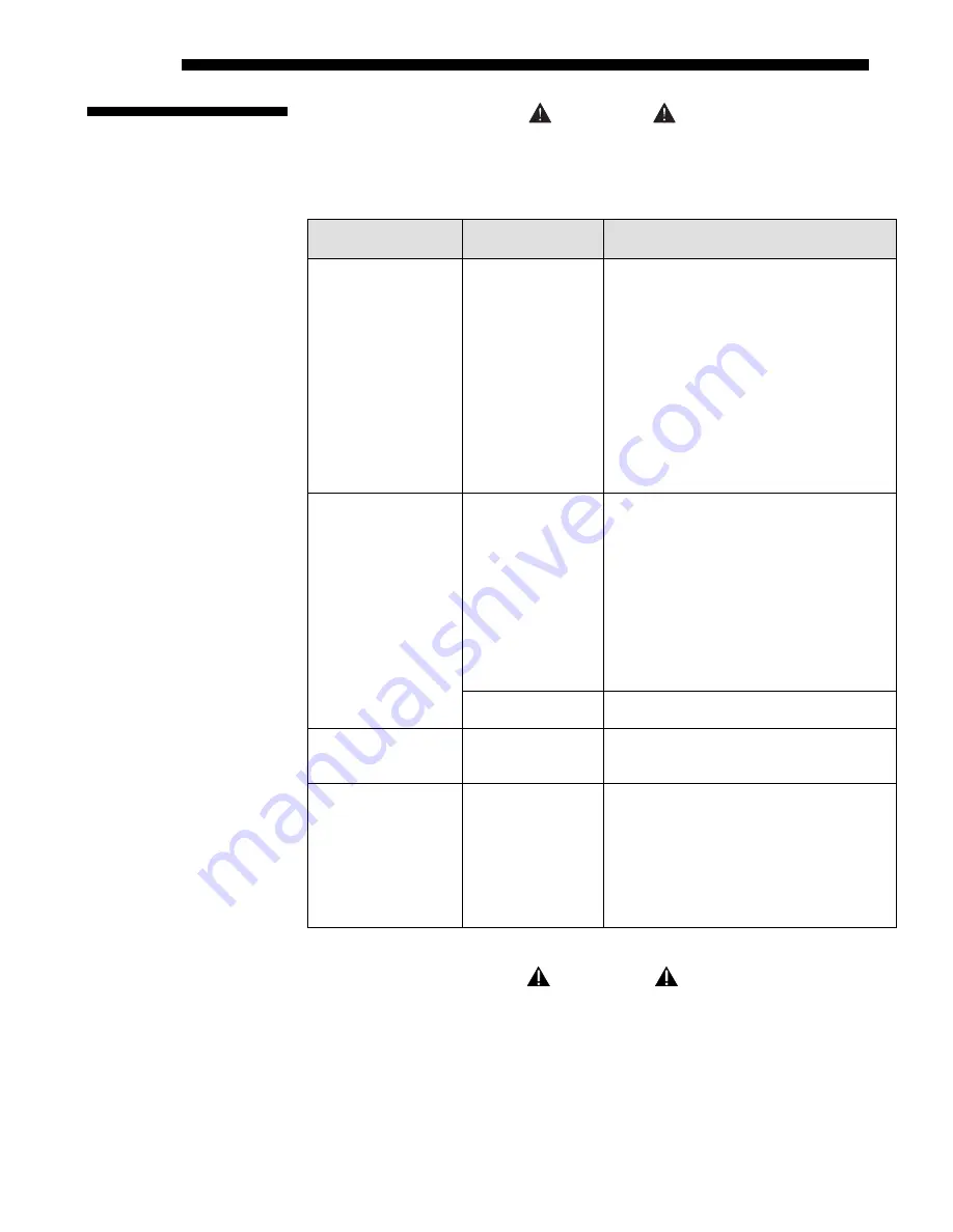
Table 4.1. Maintenance Guide 

Part Description 

Frequency 

Action 

Lens  

As required 

CLEAN:

 Clean if absolutely necessary. A 

small amount of dust on the lens has very 
little affect on picture quality. 

To clean: 

Apply a solvent such as acetone, 

alcohol or vinegar sparingly to clean, lint-
free lens tissue. Wipe across the surface of 
the lens. Do not scrub or rub tissue in 
circular motion, this will scratch the lens. 
Do not reuse tissue. Do not use cleaning 
tools treated with Ether. If particles still 
appear on the lens, try using compressed air 
to remove. 
 

As required 

CLEAN:

 Clean if absolutely necessary. 

Never touch the glass surface of the lamp. 
Fingerprints left on the glass will seriously 
degrade lamp performance or cause 
“hotspots” which can lead to an 
accumulation of intense heat in the touched 
area and cause the lamp to shatter. 

To clean:

 Wait until lamp is cool. Moisten 

a clean, lint-free cotton cloth with isopropyl 
alcohol and gently rub the surface of the 
glass in a circular motion until clean. 

Lamp  


1000 hrs or sooner 
if required 

REPLACE:

 Refer to 

4.4


Lamp and Filter 

Replacement

 procedure later in this section. 

Filters 

Whenever a lamp is 

replaced or sooner 

if required 

REPLACE:

 Do not reuse old filters. Use 

the filter provided in the Christie Lamp and 
Filter Kit.  

Covers (External) 

As required 

CLEAN:

 Clean dust from external covers 

using a clean, lint free cotton cloth as 
required.  

NOTE:

 Before cleaning the modules, it is 

recommended that you install the lens cap. 
This will keep dust particles from settling 
on the glass surface of the lens. 


 WARNING 


Proper face shield and protective gloves are required if 

the lamp module is removed from the projector. 


4.2 Cleaning 

Содержание Mirage S+

Страница 1: ...nversion 2 29 3 1 Overview 3 1 3 2 Projector Basics 3 1 3 3 Using the Keypads 3 4 3 4 Navigating the Menus 3 12 3 5 Using Inputs and Channels 3 16 3 6 Adjusting the Image 3 21 3 7 Adjusting System Par...

Страница 2: ...6 Software v1 2d A Glossary A 1 B Remote Keypad B 1 C Serial Communication Cables C 1 D Throw Distance D 1 E System Integration E 1 F Optional Input Modules F 1 NOTE Due to continuing research all inf...

Страница 3: ...distinct needs The stereoscopic Mirage S projector provides 3D solutions for power walls simulation and entertainment venues Roadster models include an additional input module as well as integral hard...

Страница 4: ...tors accept data graphics and video input signals for projection on to front or rear flat screens High brightness light is generated by an internal Bubble lamp and then modulated by three DMD digital...

Страница 5: ...ontact your dealer or Christie In many cases any necessary servicing can be performed on site If you have purchased the projector fill out the Purchase Record below and keep with your records In addit...

Страница 6: ......

Страница 7: ...panel at the rear of the projector and connector your source to the appropriate input INPUT 1 upper right area RGB input via BNC connectors INPUT 2 left of BNCs digital or analog signals DVI I from a...

Страница 8: ...lease followed immediately by Press to toggle from the off state The LCD Status Display Window will display Powering Up and then Power On Figure 2 1 while the 2 Digit Status Error Code Window will dis...

Страница 9: ...high brightness quality output final display quality could be compromised if the projector is not properly installed This subsection discusses issues you should consider before proceeding with a fina...

Страница 10: ...either orientation hoist an individual projector or up to 3 projectors in a stack Figure 2 5 Top Rigging Points RULES FOR ALL HOISTING Use at least 4 rigging points for hoisting up to 3 projectors Co...

Страница 11: ...ety Points This procedure applies to one or more projectors To hoist a stack first stack 2 or 3 projectors according to the stacking procedure included in this manual Never stack or hoist more than 3...

Страница 12: ...at each required location Figure 2 9 to prevent sliding NOTES 1 Use at least 4 rigging points for all hoisting 2 Use straps clamps or cabling with load capacity adequate for the total projector weight...

Страница 13: ...a secure table or cart Place one projector on its side to access its adjustable feet and stacking legs Figure 2 10 Orient the other projector in either upright or inverted position as required remembe...

Страница 14: ...11 If upright extend legs on top projector shown If inverted extend legs on bottom projector IMPORTANT Extend the stacking legs equally by at least 1 inch Loosen the rear stacking leg nuts On the rea...

Страница 15: ...es in 3 stacking mounts and 3 stacking legs On each stacking mount turn the adjusting wheel slightly until the hole in the top portion of the mount lines up with the hole in the stacking leg Figure 2...

Страница 16: ...r In floor mount or table mount i e non hoisted stacks you will align to the bottom projector as shown in drawings below In hoisted stacks align to the top projector Leg nuts must be loosened before a...

Страница 17: ...offset adjustment or turn the front stacker IF THE CENTER LINES FORM AN X This indicates that the projectors and images are slightly tilted in relation to one another Turn one mount to raise one side...

Страница 18: ...audience space Projector is unobtrusive Projector cannot be accidentally moved Installation is more permanent It is more difficult to access the projector Rear Screen Floor Mount Installation ADVANTA...

Страница 19: ...s its wide viewing angle similar to that of a flat screen for front screen projection Optical screens take light from the projector and redirect it to increase the light intensity at the front of the...

Страница 20: ...ness of this projector is well suited for locations where ambient lighting might be considered less than ideal for projection Even a typical room or large auditorium fully lit with ceiling lights and...

Страница 21: ...tiplied by the throw ratio of the installed lens Once you know your screen size and lens you can estimate throw distance needed For example Screen Width 10 feet Lens Type is 0 7 1 Throw Distance TD 10...

Страница 22: ...motorized offset function Starting with no offset the image from this projector can be moved left or right by a maximum distance of 350 pixels for SXGA resolution resulting in 75 of the image displaye...

Страница 23: ...d at any vertical angle i e you can tilt the face of the projector up or down as much as desired for your installation Side to side tilt however must not exceed 15 Figure 2 22 Keeping the projector fa...

Страница 24: ...erfaces slide into the remaining unused option slot and can be done while the projector is running NOTES 1 See Section 6 Specifications for details regarding compatible inputs 2 Use high quality shiel...

Страница 25: ...menu See 3 6 Adjusting the Image 2 To connect YPbPr signals such as from DVDs or analog HDTV sources to INPUT 1 use the red green and blue BNCs as described in YPbPr Signals below Connect a YPbPr sign...

Страница 26: ...d through to one or both of the module s BNC outputs NOTE Selection of these inputs is described in 3 3 Using the Keypads Connect a compatible SMPTE 292M or SMPTE 259M C source s to one or both of the...

Страница 27: ...ial communication cable between the computer and the projector serial port labeled RS232 IN this 9 pin connector is located on the input panel at the rear of the projector Figure 2 28 In the Communica...

Страница 28: ...bility The voltage levels of this signal can damage incompatible equipment Ethernet Communications To add the projector to an existing Ethernet network with other equipment such as controllers and oth...

Страница 29: ...ake sure the projector is connected to the network before attempting to change its IP address Regardless of how it is assigned once a projector has a valid and unique address it will respond to comman...

Страница 30: ...the first projector already connected to the computer controller to the RS232 IN connector of the next projector in the chain Continue connecting projectors in this manner until you ve reached the la...

Страница 31: ...baud rate In addition set the Network Routing to RS232 and RS422 Joined if you want to reach all projectors NOTES 1 To avoid damage connect only properly wired serial communication cables See Appendi...

Страница 32: ...T On some Ethernet networks firewall restrictions may require that the port number of the projector be changed from its default of 3002 If so enter a new port number in the Ethernet Settings menu or i...

Страница 33: ...tor 3 will respond to the RS422 controller To isolate just Ethernet communications select RS232 and RS422 Joined only projector 1 will respond via Ethernet The North American rated line cord is provid...

Страница 34: ...the image orientation from within the Configuration Menu you may prefer to do this before physically installing the projector in its final position orientation In the Configuration Menu highlight and...

Страница 35: ...ote keypad Press either Lens H or Lens V Figure 2 42 o If built in keypad Press Lens Shift and use the arrow keys Both styles of remote IR keypads ergonomic or brick rental staging can be converted to...

Страница 36: ...as its default protocol which is simply a collection of settings that determines how the IR keypad operates Once assigned a protocol remains in effect until it is changed that is a remote keypad will...

Страница 37: ...B G require v1 2d or higher software Step 4 Plug in the keypad cable if jumpers are set for wired use and replace the battery compartment cover Plug into projector wired keypad only and test NOTE If...

Страница 38: ...wired jumper setting refer back to Figure 2 44 Make sure to set jumper 4 between pins 2 and 3 as shown in the last example shaded 6 Replace battery compartment cover keeping the strain relief tie jus...

Страница 39: ...d commands that either control the projector directly or activate a system of intuitive menus Collections of settings can be defined and retained in the projector s internal memory as a custom channel...

Страница 40: ...aching safety cables when hoisting inverted projectors 4 eyebolts for top separate for non inverted hoisting NOTE 2 additional safety eyebolts required Handles For brief hand transport only Not used f...

Страница 41: ...upply is not within the specified voltage and power range Use the specified line cord VOLTMETER Displays incoming voltage level reaching the projector SWITCH BREAKER The breaker on the rear panel serv...

Страница 42: ...following keypads typically controls the projector Built in Keypad at the rear of the projection head Remote Keypad for tethered or tetherless control includes cable for connecting as a wired remote...

Страница 43: ...er toward the screen or toward the front or rear IR sensors on the projector NOTE For improved reception use an optional remote IR sensor to route the signal via a phone cable plugged into the wired k...

Страница 44: ...d remote is recommended when the rear built in keypad is inaccessible or if lighting conditions are interfering with IR transmission NOTE Batteries must remain in the remote to use the laser feature 1...

Страница 45: ...rocess in which the projector optimizes critical display parameters such as size position pixel tracking etc for the current unlocked channel These parameters are listed in Table 3 1 An Auto Setup can...

Страница 46: ...switches to either INPUT 5 or INPUT 7 depending on which of the Dual SD HD SDI Module inputs A or B was last used Press Input 5 again to display from the other Dual SD HD SDI Module input Input 6 Pre...

Страница 47: ...hat light areas do not become white i e crushed Conversely low contrast causes dim images See 3 6 Adjusting the Image Image Settings subsection Gamma NOTE This is the same as Gamma in the Image Settin...

Страница 48: ...d Shutter briefly to toggle the internal mechanical shutter blade closed or open with a single keystroke Or press and release Shutter followed immediately by shutter on closed or shutter off open to g...

Страница 49: ...r number Keypad commands will then affect all projectors in the chain NOTE The Broadcast Keys option in the Communications menu must be selected for only one any projector in a serial network The keyp...

Страница 50: ...2 for the Image Settings menu Or use the keys on any keypad to highlight the desired option then press The corresponding function menu or pull down list of further options will then appear With a func...

Страница 51: ...y to PIP secondary images only Most of the function menus allow you to change settings by using slidebars checkboxes and pull down lists To select a slidebar toggle a checkbox status or view a pull do...

Страница 52: ...s For quick access you access Gamma Brightness and Contrast slidebars without traveling the menu system For example simply press Cont to immediately display the same contrast slidebar accessed with th...

Страница 53: ...the cursor forward or to move the cursor backwards as desired EDIT A CHARACTER To edit a highlighted character use and to scroll through the alphabet numbers spaces and punctuation available When the...

Страница 54: ...t 5 or Input 6 describes the source signal according to which input slot it is connected SWITCH TO AN INPUT IN EITHER ONE OF TWO WAYS Pressing the appropriate direct key Input 1 Input 2 Input 3 Input...

Страница 55: ...may display a channel list or not depending on what you have defined for Display Channel List see Menu Preferences later in this section In order to access channels by using Chan on the keypad you mus...

Страница 56: ...ight with the active channel highlighted WHAT APPEARS IN CHANNEL SETUP MENU This menu lists all channels defined so far and indicates where they connect on the projector s rear input panel The far lef...

Страница 57: ...EL highlight the desired channel in the Channel Setup menu then press Func to go to the Channel Copy Delete submenu Select Copy and press Enter a new channel will be created It is identical to origina...

Страница 58: ...el Edit submenu From the presentation level press Menu to display the main menu To display the Channel Setup menu press or move the highlight to the Channel Setup option and press Enter The Channel Se...

Страница 59: ...nge Channel Edit settings for the next channel in the Channel Setup list The most commonly used options for image adjustments are accessed through two menus Size and Position Menu and Image Settings M...

Страница 60: ...nu press Exit or Menu Resize Presets Select a Resize Presets option to quickly display an image in its native resolution or to automatically resize an image to closely fill the projector s native reso...

Страница 61: ...izing will center a small image within a black border the black border areas are unused areas See below Select FULL SCREEN to use all pixels 1400 x 1050 for displaying the image regardless of source o...

Страница 62: ...quency for most sources For best results use a good test pattern such as a smooth gray consisting of a clear pattern of black and white pixels or a similar half on half off graphic image such as the W...

Страница 63: ...ull resolution to use and pixels in the surrounding borders are turned off You can also specify a specific active input window size by adjusting one or more Blank settings For example if you have blan...

Страница 64: ...ge without affecting its size or position Changes made to the Image Settings menu are applied immediately and are saved when you exit the menu press Exit or Menu Options not available for the projecto...

Страница 65: ...amma is used to fine tune the gamma table currently in use ranging from 1 3 2 2 default If excess ambient light washes out the image and it becomes difficult or impossible to see details in dark areas...

Страница 66: ...space for these analog signals is automatically determined by the projector in some circumstances you may wish to override this and manually set a specific color space NOTE For many digital signals o...

Страница 67: ...and Japan NTSC 4 43 A tape only standard for partially translated hybrid signals PAL Most of Europe China Australia some of S America some of Africa PAL M Brazil PAL NC Argentina Chile other Latin Ame...

Страница 68: ...s that is the drives and blacklevels for each of the three colors red green and blue ensure that images from analog sources other than decoded video have maximum contrast without crushing black or whi...

Страница 69: ...s producing skewed input levels Continue with Step 5 5 Temporarily enable Auto in the Input Levels submenu Wait for all 6 values to stabilize Alternatively do not use Auto reduce blacklevels manually...

Страница 70: ...n the Peak Detector checkbox NOTE The Peak Detector will initially render the grayscale as a uniform gray field before adjustment or extreme crushing 2 Display one primary color NOTE Selecting Auto Co...

Страница 71: ...amma curve is a value of 2 2 and is correct for most signal conditions Although the projector automatically applies either the graphics or video curve according to what type of incoming signal is dete...

Страница 72: ...ts to 6500K until changed All four User options default to SD Video unless the user has redefined them 2 Factory defined color primaries which ensure consistent color gamut from projector to projector...

Страница 73: ...ng L R shutters in 3D glasses a total frame delay setting of two or multiple of two may be more useful If set too high or low frame locking will not be possible most sources require approximately 50 l...

Страница 74: ...s connected between the projector s GPIO port and a server Slidebar values indicate the number of lines that are delayed FRAME LOCK ENABLE This option allows the projector to control the output frame...

Страница 75: ...l will be magnified An ideal detail threshold is one in which high frequencies that are causing objectionable noise are not magnified when using Detail but frequencies which can help sharpen an overly...

Страница 76: ...on screen menus To create a custom menu location quickly choose a preset that is closest to the desired location Then adjust Horizontal Shift and Vertical Shift slidebars to move the menu to the desi...

Страница 77: ...e current splash screen content in projector memory Settings in the Communications submenu define and control how single or multiple projectors are linked with each other and with a controlling device...

Страница 78: ...Ethernet messages on their respective paths instead of being broadcast to the other types of ports In Figure 3 19A RS422 controls only the projector to which it is connected In Figure 3 19B either RS...

Страница 79: ...for and used by common IP applications SUBNET MASK AND DEFAULT GATEWAY The Subnet Mask and Default Gateway are automatically assigned when DHCP is enabled If a static IP is being used the IP must be...

Страница 80: ...servers support querying for devices DEVICE DESCRIPTION More information that is returned when a device query has been done Broadcast Key Enter a checkmark if you want keypad commands sent to one pro...

Страница 81: ...the wired keypad you must use a different keypad the built in or an IR remote keypad to select off This safeguard prevents you from accidentally disabling the wired keypad during use In the Configurat...

Страница 82: ...e front of the projector and which primarily affect blacklevels NOTES 1 There is a centerline both horizontal and vertical in the Edge Blending test pattern The intersection of these lines is the true...

Страница 83: ...X Y Use this submenu if you want to create alter or copy a color gamut i e color adjustment Controls in this menu define the precise hue of each primary color component red green blue and white used...

Страница 84: ...ary color red green blue and white by using more or less of it in relation to the other colors NOTE A Color Saturation adjustment defines the corresponding x y coordinates shown in the Color Adjustmen...

Страница 85: ...lows the projector to display multiple aspect ratios correctly sized and positioned on the same screen It s useful when working with a variety of source types that might differ in size and or aspect r...

Страница 86: ...er special setup parameters Colors can also be enabled disabled by entering the corresponding function code listed on the back of the standard remote keypad Odd Pixel Adjustment NOTES 1 Factory set an...

Страница 87: ...displayed as a mid level gray When used with a 16 step grayscale pattern in which the two black and white bands are known to be at opposite edges of the image you can watch these isolated areas while...

Страница 88: ...een done the projector will automatically recall these settings from memory when it s being powered up and a motion calibration will not take place A full calibration performs both a reference and mot...

Страница 89: ...or fade into the new image Options for enabling and controlling PIP and Seamless Switching all reside in the same menu Note however that because both features utilize the projector s double processing...

Страница 90: ...re in Picture and Switching menu Use the first of six options in the PIP and Switching menu to enable and define how you want to use PIP Swap Main and PIP Image Toggle the current picture in picture r...

Страница 91: ...ing submenu control switching parameters 2 Disable PIP in order to work with Seamless Switching 3 Disable PIP and Best Switching for Interlaced sources 35kHz Seamless Switching is the ability to insta...

Страница 92: ...Main menu To use the keys in this manner all of the time even with single displays select Always For normal keypad function select Never default Set to When PIP Active to activate number keys only wh...

Страница 93: ...cific wattage appropriate for the installed lamp or set a desired intensity brightness to maintain Although there are exceptions generally higher light output or higher power settings can shorten lamp...

Страница 94: ...ntain the desired brightness Keep in mind that once the lamp power reaches its maximum wattage see Power above this tracking is no longer possible At this point the lamp will gradually begin to dim as...

Страница 95: ...emain as they were for the previous lamp and can be changed at any time Figure 3 27 Recording the New Lamp Serial Number NOTE Enter a serial number only if you have just installed a new lamp This will...

Страница 96: ...cisely match color and intensity from image to image so that the full wall is as uniform as possible This matching is typically done in conjunction with brightness uniformity and edge blending Prelimi...

Страница 97: ...both the setup and maintenance of a seamless wall 1 Set up and optimize all projector settings You can ignore color temperature since you will be redefining color performance in this procedure but do...

Страница 98: ...r a full field display of the corresponding color Alternatively use the Color Saturation menu for these adjustments or to fine tune These coordinate adjustments move the three color points closer toge...

Страница 99: ...creens Although the Brightness Uniformity control can be used for a stand alone projector it is particularly useful for setting up and maintaining tiled images that form a cohesive display wall in whi...

Страница 100: ...en WHITE UNIFORMITY SLIDEBARS White Uniformity slidebar values may not reduce to 0 Each slidebar adjusts overall light output in a specific screen zone but the value shown represents the current setti...

Страница 101: ...ghtly to recover center matches Step 2 Adjust Color level of red green blue in 8 Zones NOTES 1 At this point ignore the brightness of individual zones 2 Always ignore menu colors 2a On each screen com...

Страница 102: ...formity first note that each edge adjustment also affects the rest of the screen slightly Keep all edges just slightly lower than the center light output rather than matching light output precisely Ot...

Страница 103: ...ll In addition avoid high gain screens whenever possible the optical performance of such screens demands minimal image offset thus projectors must be located very close to one another Note too that th...

Страница 104: ...cess via Configuration menu then Geometry and Color submenu then Edge Blending The More option opens the second page of the Edge Blending submenu Main Functions Use standard edge blending controls to...

Страница 105: ...adjacent images Toggle the Show Blending Overlap off to reactivate the blend effect NOTE Show Blending Overlap appears as Reserved when ChristieTWIST is installed Other Functions For convenience the...

Страница 106: ...et all blend widths to 0 Go to More and set everything in the Edge Blending 2 menu to 50 Figure 3 38 Set Starting Points for Each Projector 4 SET BLEND WIDTH On one projector increase the Blend Width...

Страница 107: ...zones If a given Edge Blend zone width is set to 0 i e no blend on that side then the corresponding BLB zone is disabled It only becomes accessible when that Edge Blend zone is active 1 Start with 2...

Страница 108: ...ons document available at the Christie website VIA WEB INTERFACE Connect your PC to the projector s Ethernet port In your web browser Internet Explorer for example enter the IP address of the projecto...

Страница 109: ...For example if you specify a channel number that is not available the message Invalid Channel will appear Or if you try to enter the wrong password you ll see Invalid Password Press or Exit to clear t...

Страница 110: ...A system warning indicates that a system malfunction has been detected see Status LED Codes below A system warning message replaces any input signal message and disappears when the input signal statu...

Страница 111: ...ailed 61 Unable to program DigMux PLD 62 Unable to program Control PLD 63 Unable to program Bubks PLD 64 Unrecognized ROM type 65 Write to flash ROM failed 66 General TIPM failure 67 Downloaded code w...

Страница 112: ......

Страница 113: ...personnel ONLY Observe and follow all warnings and instructions marked on the projector The exclamation point within the equilateral triangle alerts the user to important operating and maintenance se...

Страница 114: ...nplugging it This provides enough time for the internal lamp cooling fans to cool the lamp and to automatically shut off Cool completely before handling WARNING Use only lamps supplied by Christie Use...

Страница 115: ...tend projector feet as necessary Do not push objects of any kind into the projector through the ventilation openings They may touch dangerous voltages or short out components resulting in a fire or sh...

Страница 116: ...ill seriously degrade lamp performance or cause hotspots which can lead to an accumulation of intense heat in the touched area and cause the lamp to shatter To clean Wait until lamp is cool Moisten a...

Страница 117: ...S 20K Lamp and Filter Replacement Kit manufactured by Christie Digital Systems See Table 4 2 below Table 4 2 Lamp and Filter Kits Projector Model Lamp Type Watts Lamp Filter Kit Required Roadster S 1...

Страница 118: ...rmed by a qualified service technician Cool the lamp completely and handle by the housing only Install the correct wattage lamp supplied by Christie see above and read the Lamp Replacement procedure i...

Страница 119: ...4 2 4 REMOVE LAMP RETAINING BAR Remove the two 2 screws that secure the retaining bar along the bottom edge of the lamp module using a 2 Phillips screwdriver See Figure 4 3 Swing the bar aside it is...

Страница 120: ...ates initial contact with these connectors push firmly at this point WARNING Improper installation could cause a serious meltdown inside the projector 7 RE INSTALL LAMP RETAINING BAR Position the reta...

Страница 121: ...l now begin to log time for the new lamp IMPORTANT If you neglect to enter a serial number the lamp timer will not reset to 0 and will therefore be inaccurate The lamp life limit may then expire prema...

Страница 122: ...insert the new one Follow the airflow arrows for correct orientation See Figure 4 7 In the Roadster S 20K which has a rhomboid shaped filter insert the sharply angled corner first place fully back on...

Страница 123: ...g NOTE If necessary a lens can be swapped out while the projector is running but this can result in dust being drawn into the projector Avoid if possible Before removing or installing any lens turn of...

Страница 124: ...secured and the lens release button CLICK Secure lock down screws optional For added stability secure the adjustment screws provided on the lens retaining ring see Figure 4 If you have installed a lar...

Страница 125: ...atterns then cycle patterns with keys 5 Is the input selected Check connections Blacklevels seem too high Reduce Brightness setting Image appears squeezed or vertically stretched into center of screen...

Страница 126: ...el sampling clock is incorrect for the current source 2 Resizing vertical stretch and positioning options may be improperly adjusted for the incoming source signal 3 You may need an anamorphic lens fo...

Страница 127: ...stance between the input source device and the projector is greater than 25 feet signal amplification conditioning may be required 5 If the source is a VCR or off air broadcast detail may be set too h...

Страница 128: ...to a network before you attempt to change its IP address and always cycle power off on to implement the new IP address 3 Make sure to save any address change and re boot to implement 4 If you still ha...

Страница 129: ...ge S 14K 450 ANSI 1500 full field in Roadster S 20K Colors and Gray Scale Default Optical Color temperature at grays 5150K 6750K Range of adjustment 3200K 9300K Displayable colors 1 1 billion min Gray...

Страница 130: ...10 bit Input levels R B G Y with sync R G B without sync Pb Pr 1 0Vp p 2 dB 0 79Vp p 1 26Vp p 0 7Vp p 2 dB 0 56Vp p 0 88Vp p 0 7Vp p 2 dB 0 56Vp p 0 88Vp p DC offset 5V Nominal impedance 75 ohms Max r...

Страница 131: ...separate H V Separate H and V Bi level or tri level sync on green Bi level or tri level composite Serrations and or Equalization pulses MacroVision for stnd prog video Polarity for composite or separ...

Страница 132: ...Modulation carrier frequency 38 kHz and 455 kHz Encoding method Bi phase IR reception range 100 ft Ethernet Number of ports 1 Standard 100Base TX Connector type Female RJ 45 Maximum throughput 115 2...

Страница 133: ...input coupler Roadster S 12K Roadster S 16K Mirage S 14K Roadster S 20K 15 A 20 A 20 A n a Type of connector projector Roadster S 12K Roadster S 16K Mirage S 14K Roadster S 20K IEC320 C14 IEC320 C19 I...

Страница 134: ...age S 14K UL 60950 and CAN CSA C22 2 No 60950 2000 3rd edition bi national IEC 60950 1999 3rd edition CCC China Compulsory Certification FDA approval for laser in remote IR keypad Roadster S 20K UL 60...

Страница 135: ...Stacking mounts Integral rigging hardware Mirage S 14K IR Remote lite keypad batteries included Line cord Roadster Mirage S User s Manual 3D Stereo Sync Cable Using 3D in Mirage CD Using 3D in Mirage...

Страница 136: ......

Страница 137: ...he ratio of the width of an image to its height such as the 4 3 aspect ratio common in video output Can also be expressed as a decimal number such as 1 77 1 85 or 2 39 The larger the ratio or decimal...

Страница 138: ...output cable The degree of difference between the lightest and darkest areas of the image The alignment of the red green and blue elements of a projected image so that they appear as a single element...

Страница 139: ...ncy For interlaced signals the frame rate also known as field rate is one half of vertical frequency The ability of a screen to direct incident light to an audience A flat matte white wall has a gain...

Страница 140: ...shaped image It is caused when the screen and lens surface are not parallel or by poor Keystone adjustment The time from input to output The reproduction of the horizontal and vertical size of charact...

Страница 141: ...keypad protocols adjacent projectors can be controlled independently with their remote IR keypads A selectable menu item that unfolds into a list of options pertaining to it A manufacturer of a digita...

Страница 142: ...isk players used primarily in France SECAM Sequential Couleur M moire signals are similar in resolution and frequency to PAL signals The primary difference between the two standards is in the way colo...

Страница 143: ...e signal that is used by display devices such as projectors to generate an image This term also refers to the output of video tape disk players and computers An optional device that converts NTSC 3 58...

Страница 144: ......

Страница 145: ...Appendix B Keypad Reference Roadster Mirage S User s Manual B 1 Figure B 1 Remote Keypad...

Страница 146: ...KEYPAD REFERENCE B 2 Roadster Mirage S User s Manual Figure B 2 Brick Rental Staging Remote Roadster...

Страница 147: ...ication with the projector so that it can be controlled remotely from a PC or other controller From a PC connect a standard 9 wire RS232 serial cable to the RS232 IN port located on the side of the pr...

Страница 148: ...SERIAL COMMUNICATION CABLES C 2 Roadster Mirage S User s Manual...

Страница 149: ...screen Once you know the screen size and lens type present you can calculate the precise throw distance you require by using the appropriate formula as found in this appendix Throw distance is the dis...

Страница 150: ...163 1375 1 8 2 5 Min 1 8301 x screen width cm 5 828 cm Max 2 6019 x screen width cm 3 251 cm 56 536 145 1375 2 5 4 5 Min 2 6147 x screen width cm 5 8132 cm Max 4 7718 x screen width cm 25 91 cm 66 536...

Страница 151: ...47 1656 646 1 45 1 8 1 Lens 1 45 Zoom Image Width Throw Distance cm in cm in 160 62 256 100 175 68 278 109 190 159 300 117 205 80 323 126 220 86 345 134 235 92 367 143 250 98 389 152 265 103 411 160 2...

Страница 152: ...372 550 215 1001 390 565 220 1028 401 570 222 1037 405 585 228 1065 415 600 234 1092 426 615 240 1120 437 630 246 1147 447 645 252 1175 458 660 257 1202 469 675 263 1229 480 690 269 1257 490 705 275 1...

Страница 153: ...535 209 1379 538 550 215 1418 553 565 220 1457 568 580 226 1496 583 595 232 1535 599 610 238 1574 614 625 244 1613 629 640 250 1652 644 655 255 1691 659 670 261 1730 675 685 267 1769 690 700 273 1808...

Страница 154: ...69 575 224 1498 584 590 230 1537 599 605 236 1576 615 620 242 1615 630 635 248 1655 645 650 254 1694 661 665 259 1733 676 680 265 1772 691 695 271 1811 706 710 277 1851 722 725 283 1890 737 740 289 19...

Страница 155: ...207 2503 976 545 213 2575 1004 560 218 2646 1032 575 224 2718 1060 580 226 2742 1069 605 236 2861 1116 620 242 2933 1144 635 248 3004 1172 650 254 3076 1200 665 259 3147 1227 68 27 299 116 695 271 32...

Страница 156: ...031 595 232 2712 1058 610 238 2780 1084 625 244 2849 1111 640 250 2917 1138 655 255 2986 1165 670 261 3055 1191 685 267 3123 1218 700 273 3192 1245 715 279 3260 1272 730 285 3329 1298 745 291 3398 132...

Страница 157: ...37 550 215 4051 1580 565 220 4162 1623 580 226 4273 1667 595 232 4384 1710 610 238 4496 1753 625 244 4607 1797 640 250 4718 1840 655 255 4829 1883 670 261 4940 1927 685 267 5051 1970 700 273 5162 2013...

Страница 158: ......

Страница 159: ...al cable required for connecting the external device to the projector s GPIO connector whether it s a standard serial cable or a custom one must be compatible with the external device The GPIO connect...

Страница 160: ...st configuration for pin 2 GIO C2 O Reply with pin 2 configuration as output GIO 2 Request the state of pin 2 GIO H Reply with pin 2 state as high Use the serial command RTE to specify an action that...

Страница 161: ...dule enables incoming SD or HD serial digital data to be tiled across multiple screen displays overlapped for extra bright displays or distributed to additional projectors for multiple same image scre...

Страница 162: ...A Features Accepts 3 4 or 5 wire RGB video sync on green composite sync or separate horizontal and vertical sync Accepts YPbPr composite on green and Y C on red blue BNC connectors for RGB signal inpu...

Страница 163: ...gnals NOTE non functional Buffered loop through video outputs The PC250 Analog Input Module receives analog RGB input signals from IBM PC compatibles or Macintosh computers Video inputs are 75 termina...

Страница 164: ...rial Digital Input Module SDI accepts a serial digital 4 2 2 component video signal YCbCr via a single SERIAL IN BNC connector The signal can loop through the SERIAL OUT BNC out to another device such...

Страница 165: ...mity Menu 3 63 Broadcast Key 3 42 Broadcasting 3 11 Bubble Xenon Lamp See Lamp C Channel Copy Delete 3 19 Locked 3 21 Number 3 17 Selection 3 18 Signal Type 3 18 Using 3 18 Channel Key 3 7 3 17 Channe...

Страница 166: ...Exit Key 3 11 F Film Mode Threshold 3 37 Filter Replacement Schedule 4 2 Filter Image Adjustment 3 27 Flying Projector See Projector Hoisting Focus 2 3 2 29 3 2 Folded Optics 2 18 Font Size Menu 3 38...

Страница 167: ...wer 3 55 Language Select 3 37 Laser Key 3 12 LCD Status Display Window 3 4 LED Status Codes 3 72 Lens Adjustments 2 3 List Specifications 6 2 Offset 3 2 Replacement Procedure 4 11 Lens Focus Keys 3 11...

Страница 168: ...s Use of 3 14 Purchase Record 1 3 Q Quick Set Up 2 1 R Remote Keypads Jumper Settings 2 31 Resizing 3 22 Default 3 22 Resolution 6 1 RGB Connection 3 3 Sources 2 18 Rigging Hardware Attaching 2 6 RS 2...

Страница 169: ...15 Definition 2 15 Time outs 3 13 Troubleshooting Ethernet 5 4 Lamp 5 3 Power 5 1 V Ventilation Importance of 4 3 Vertical Offset Adjusting 3 2 Vertical Position 2 15 3 25 Vertical Stretch 3 24 Video...

Отзывы: