68
DWU951 (DD1-WU80P/81P) / DWX951 (DD1-WX80P/81P) / DXG1051 (DD1-X100P/101P)
DWU951/DWX951/DXG1051 Service Manual
020-000674-01 Rev.1 (01-2014)
Page 68 / 118
NOTE:
It is not necessary to detach ENGINE assembly before
detaching the ADAPTER PCB.
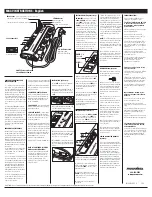
Disassembling
Disconnect the cable CNLAD, and remove 2 screws to
detach ADAPTER PCB.
Assembling
Connect CNLAD to the ADAPTER PCB, and screw down
the PCB as before.
z
! !#Q^#
K!+J###
torque: 0.18~0.22N
·
m
Connect CNLAD.
DC RELAY PCB
NOTE:
It is not necessary to detach ENGINE assembly before
detaching the fans.
Disassembling
1) Disconnect the cable from the DC RELAY PCB (LAMP1
UP FAN) or MAIN PCB (LAMP2 UP FAN).
2) Remove 3 screws and detach the LAMP UP FAN DUCT.
3) Remove each 2 screws fastening the fan.
Assembling
1) Prepare the fan cable, and check the wiring around the
LAMP UP FANs before attaching the fans to avoid pinching
the wires or letting it shorten.
2) Screw down the fan, and the LAMP UP FAN DUCT as
before.
3) Wire and connect the fan cables.
Wiring
Prepare the fan cable as shown on the right.
? >K*!%*Q>"#
cables around the fans and LAMP UP FAN DUCT.
z
@!#~#*!
K+©#
torque: 0.45~0.55N
·
m
K+###
torque: 0.68~0.88N
·
m
LAMP1 UP FAN
LAMP2 UP FAN
50mm
< LAMP1 UP FAN>
95mm
< LAMP2 UP FAN>
Turn twice and bind it
with tape (W=9mm)
60mm
Pass only LAMP1 UP FAN
cable and CWC MOTOR
cable through this clamp.
LAMP1 UP FAN
Bind the wire with
tape (W=9mm).
*?"??§+
cable of the CW under the hook.
LAMP2 UP FAN
Содержание DD1-WU80P
Страница 1: ...DWU951 DWX951 DXG1051 Service Manual 020 000674 01...
Страница 2: ......
Страница 120: ...DWU951 DWX951 DXG1051 DWU951 DWX951 DXG1051 Service Manual 020 000674 01 Rev 1 01 2014 Page 118 118...
Страница 149: ......
Страница 150: ......


