INST No INE -403-0P0
−
41
−
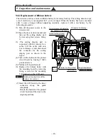
9.4.5 Replacement of power supply unit
(1) Turn off the power source to the
detector unit.
(2) Open the door of detector unit.
(3) Disconnect the connection cable
and take out the connection cable
from the cable inlet.
(4) Pull out the output board from the
case inside by loosing two M3 pan
head screws and by disconnecting
the connector (14-pin).
(5) Pull out the power supply unit by
loosing M3 nut and two M3 pan
head screws and by disconnecting
two connectors (10-pin, 2-pin).
(6) Connect the connector to a new
power supply unit and assemble it
by reversing the removing
procedure. Be careful not to step
the connection cable.
(7) Connect the connector to the output
board taken out and fix it to the
case inside.
(8) Connect the connection cable and
return the door to the original position.
9.5 Ram clearing
If the abnormal condition of the detector unit is not recovered, initialization of the RAM is
required.
(1) Turn on the power supply after pressing SEL key and
>
key simultaneously.
(2) The contents of ram will be initialized. Set the calibration curve data, etc. again.
Output board fix ing sc rews
(2- M 3 pan head screws )
Output board
Output board
c onnector (14- pin)
Pow er s up ply fix ing sc rews
(2- M 3 pan head screws )
Power supply
connec tor(10- pin)
M 3 nuts
and spring
washers
Power supply
connector(2- pin)
P ower s upply
Fix it so that this part enters into the
dent departm ent of out put board when
attac hing the out put boar d.
9. Inspection and maintenance

