EN
20
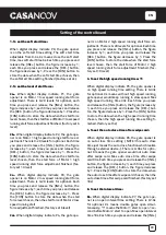
1. To set the soft start time:
When digital display indicate P0, the gate opener
is on the soft start time setting. The soft start time
adjustable from 0-6s, 0s means close the soft start
time, max soft start time 6s. Each time you press and
release the [INC+] button, the figure increase by 1;
each time you press and release the [DEC-] button,
the figure decrease by 1. Press the [FUN] button to
store the data when the soft start time chosen, then
the soft start time setting finished (Factory set 2s).
2. To set the level of stall force:
2a--
When digital display indicate P1, the gate
opener is on Motor 1 low speed running stall force
adjustment. There is 0-20 levels for optional, each
time you press and release the [INC+] button, the
figure increase by 1; each time you press and release
the [DEC-] button, the figure decrease by 1. Press the
[FUN] button to store the data when the stall force
level chosen, then the stall force of Motor 1 low speed
running stall force adjustment finished. (factory set 6
level)
2b--
When digital display indicate P2, the gate ope-
ner is on Motor 1 high speed running stall force ad-
justment. There is 0-20 levels for optional. Each time
you press and release the [INC+] button, the figure
increase by 1; each time you press and release the
[DEC-] button, the figure decrease by 1. Press the
[FUN] button to store the data when the stall force
level chosen, then the stall force of Motor 1 high
speed running stall force adjustment finished. (fac-
tory set 10 level)
2c--
When digital display indicate P3, the gate
opener is on Motor 2 low speed running stall force
adjustment. There is 0-20 levels for optional. Each
time you press and release the [INC+] button, the
figure increase by 1; each time you press and release
the [DEC-] button, the figure decrease by 1. Press
the [FUN] button to store the data when the stall
force level chosen, then the stall force of Motor 2 low
speed running stall
force adjustment finished. (factory set 6 level)
2d--
When digital display indicate P4, the gate ope-
ner is on Motor 2 high speed running stall force ad-
justment. There is 0-20 levels for optional. Each time
you press and release the [INC+] button, the figure
increase by 1; each time you press and release the
[DEC-] button, the figure decrease by 1. Press the
[FUN] button to store the data when the stall force
level chosen, then the stall force of Motor 2 high
speed running stall force adjustment finished. (fac-
tory set 10 level)
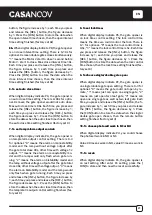
3. To set the high speed running time:
11
When digital display indicate P5, the gate opener is
on high speed running time setting. There is 0-33s
for optional. 0s means without high speed running,
gate opener would keep running in slow speed. Max
high speed running time 33s. Each time you press
and release the [INC+] button, the figure increase by
1; each time you press and release the [DEC-] but-
ton, the figure decrease by 1. Press the [FUN] button
to store the data when the high speed running time
chosen, then the high speed running time setting fi-
nished. (factory set 5s)
4. To set the auto close time after swipe card:
When digital display indicate P6, the gate opener is
on auto close time setting ( NOTE! this auto close
time just means the auto close function which realize
through external device-). There is 0-99s for optio-
nal. 0 means the gate opener would not auto close
after swipe card. Max auto close time after swipe
card 99s. Each time you press and release the [INC+]
button, the figure increase by 1; each time you press
and release the [DEC-] button, the figure decrease
by 1. Press the [FUN] button to store the data when
the auto close time after swipe card chosen, then the
auto close time after swipe card finished. (factory set
10s)
5. To set the interval time:
5a.
When digital display indicate P7, the gate ope-
ner is on open interval time setting. There is 0-10s
for optional. 0s means double gates open simul-
taneously. “1” means the Motor 1 start to open 1 se-
cond before Motor 2 start to open. Max open interval
time 10s. Each time you press and release the [INC+]
Setting of the control board
Содержание HICKER B200
Страница 5: ...EN 5 Serial Number ...
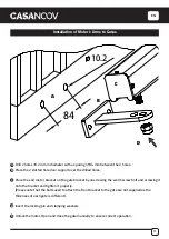
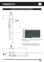
Страница 10: ...EN 10 Installation of Extended End Motor Arms to Gates USE BUBBLE LEVEL K D mm ...
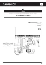
Страница 17: ...EN 17 IR OUT COM COM 12V 05 COM 06 IR 07 12V 19 20 21 22 BLUE BROWN BROWN BLUE 19 20 21 22 ...
Страница 27: ...FR 27 Numéro de série ...
Страница 32: ...FR 32 Installation des bras motorisés sur le portail K D UTILISER UN NIVEAU mm ...
Страница 39: ...FR 39 IR OUT COM COM 12V 05 COM 06 IR 07 12V 19 20 21 22 19 20 21 22 BLEU MARRON BLEU MARRON ...
Страница 49: ...DE 49 Seriennummer ...
Страница 54: ...DE 54 Installation von verlängerten Endmotorarmen an Toren K D VERWENDUNG EINER WASSERWAAGE mm ...
Страница 61: ...DE 61 IR OUT COM COM 12V 05 COM 06 IR 07 12V 19 20 21 22 BLAU BRAUN BRAUN BLAU 19 20 21 22 ...
Страница 71: ...ES 71 Número de serie ...
Страница 76: ...ES 76 Instalación de brazos de motor de extremo extendido a las puertas K D USANDO UN NIVEL DE BURBUJÀ mm ...
Страница 83: ...ES 83 IR OUT COM COM 12V 05 COM 06 IR 07 12V 19 20 21 22 AZUL MARRÓN MARRÓN AZUL 19 20 21 22 ...
Страница 93: ...PT 93 Número de série ...
Страница 98: ...PT 98 Instalação de Braços de Motor Extendidos a Portões K D UTILIZAÇÃO DE UM NÍVEL DE BOLHA mm ...
Страница 105: ...PT 105 IR OUT COM COM 12V 05 COM 06 IR 07 12V 19 20 21 22 AZUL CASTANHO CASTANHO AZUL 19 20 21 22 ...
Страница 115: ...IT 115 Numéro de série ...
Страница 120: ...IT 120 Installazione di bracci motore finali estesi su cancelli K D USARE UNA LIVELLO DELLA BOLLA mm ...
Страница 127: ...IT 127 IR OUT COM COM 12V 05 COM 06 IR 07 12V 19 20 21 22 BLU MARRONE MARRONE BLU 19 20 21 22 ...
Страница 137: ...NL 137 Serienummer ...
Страница 142: ...NL 142 Installatie van Extended End Motor Arms to Gates K D GEBRUIK MAKEN VAN LUCHTBELNIVEAU mm ...
Страница 149: ...NL 149 IR OUT COM COM 12V 05 COM 06 IR 07 12V 19 20 21 22 BLAUW BRUIN BRUIN BLAUW 19 20 21 22 ...
Страница 159: ...PL 159 Numer seryjny ...
Страница 164: ...PL 164 Instalacja ramion silnika z przedłużonym końcem do bramek D UŻYWAĆ POZIOM BĄBELKÓW mm ...
Страница 171: ...PL 171 IR OUT COM COM 12V 05 COM 06 IR 07 12V 19 20 21 22 NIEBIESKI BRĄZOWY BRĄZOWY NIEBIESKI 19 20 21 22 ...

