

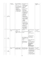


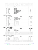
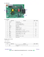
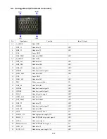


3-2. NCU Board
J1 (to Logic Board)
J2 (Modular Jack, TEL / LINE)
TEL : Pin 1 to 6
LINE : Pin 7 to 12
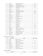
J3 (Power Supply Unit)
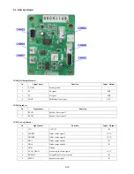
No.
Signal name
Function
Input / Output
1
A_GND
Analog ground
-
2
+12V
Analog power supply
IN
3
RX
4-wire analog reception signal
OUT
4
TX
4-wire analog transmission signal
IN
5
SNOOP
Snoop signal
OUT
6
D_GND
Digital ground
-
7
IPSEL
Terminal switch signal
-
8
+3.3V
Digital power supply
IN
9
CI1
CI detect signal 1 (1: CI 0: No CI)
OUT
10
HRD
H relay drive signal (1: ON (no ring) 0: OFF (ring))
OUT
11
CMLD
CML relay drive signal (1: ON 0: OFF)
IN
12
HOOK1
Hook detect signal (1: ON 0: OFF)
IN
13
SRD
S relay drive signal (1: ON 0: OFF)
IN
14
DCLIM
Not used
IN
15
+5.5V
Mechanical relay power supply
IN
16
D_GND
Digital ground
-
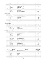
No.
Signal name
Function
Input / Output
1
VH+
External telephone line hook detect power supply
-
2
VH-
VH ground
-
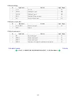
To the table of contents
To the top
<Part 3: 3. CONNECTOR LOCATION AND PIN LAYOUT ; 3-2. NCU Board>
3-9
Содержание PIXMA MP530
Страница 5: ...Part 1 MAINTENANCE ...
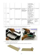
Страница 34: ... Right side c Disconnect the connector for the solenoid 1 29 ...
Страница 51: ... Service test print sample 1 46 ...
Страница 56: ... System data list sample 1 51 ...
Страница 57: ... Error transmission report sample 1 52 ...
Страница 60: ...Part 2 TECHNICAL REFERENCE ...
Страница 73: ...Part 3 APPENDIX ...