


3-3. Adjustment / Settings
(1) Paper feed motor adjustment
(2) Grease application
(3) Waste ink counter setting
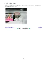
(4) White sponge sheet attachment
(5) User mode
(6) Service mode
Service mode operation
Destination settings
Waste ink amount setting
Button and LCD test
3-4. Verification Items
(1) Service test print
(2) EEPROM information print
(3) Fax report
4. MACHINE TRANSPORTATION
Part 2: TECHNICAL REFERENCE
1. NEW TECHNOLOGIES
2. CLEANING MODE AND AMOUNT OF INK PURGED
3. PRINT MODE
3-1. Normal Color Printing via Computer
3-2. Normal Grayscale Printing via Computer
3-3. Borderless Printing via Computer
3-4. Duplex Printing via Computer
3-5. Camera Direct Printing
3-6. Copying
4. FAQ (Problems Specific to the MP530 and Corrective Actions)
Part 3: APPENDIX
1. BLOCK DIAGRAM
2. WIRING DIAGRAM
3. CONNECTOR LOCATION AND PIN LAYOUT
3-1. Logic Board Ass'y
3-2. NCU Board
3-3. NCU Sub Board
3-4. Carriage Board (Print Head Connector)
4. SPECIFICATIONS
Содержание PIXMA MP530
Страница 5: ...Part 1 MAINTENANCE ...
Страница 34: ... Right side c Disconnect the connector for the solenoid 1 29 ...
Страница 51: ... Service test print sample 1 46 ...
Страница 56: ... System data list sample 1 51 ...
Страница 57: ... Error transmission report sample 1 52 ...
Страница 60: ...Part 2 TECHNICAL REFERENCE ...
Страница 73: ...Part 3 APPENDIX ...