V. INSTALLATION
A. Precautions
1) This product has been carefully adjusted and strictly inspected before packing and shipping.
To make the operation as intended, it is important to install it correctly. Service engineers
must understand the performance of the printer sufficiently, install it in the appropriate
environment with proper procedures, and operate the necessary checks.
2) Before taking the printer to the customer’s premises, the following conditions at the instal-
lation location should be confirmed:
•
Power must be directly connectable to a single socket with a supply voltage within ± 10 % of
the rated voltage (100-127V) or +6 % to -10 % of the rated voltage (220-240V.)
•
The temperatures should be in a range from 10 to 32.5 °C and the relative humidity from 20
to 80 %. Avoid areas closed to water faucets, boilers, humidifiers, or refrigerators.
•
Avoid areas near open flames, dusty locations, windy locations, areas which emit ammonia
gas, and areas directly exposed to sunlight. When exposure to direct sunlight is unavoid-
able, hanging curtains is recommended.
•
The room should be well ventilated.
•
The printer should be placed on a level surface.
•
If the printer is set up on a desk, be sure a study desk is used.
•
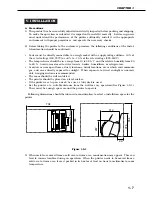
Set the printer at a suitable distance from the wall for easy operation (See Figure 1-5-1.)
There must be enough space around the printer to operate.
Following dimensions should be taken into consideration to select a installation space for the
printer.
Figure 1-5-1
3) When metals are moved from a cold area to warm area, condensation may appear. This can
lead to various troubles during an operation. When the printer needs to be moved from a
cold area to warm area, leave it packed in its box for at least an hour to acclimatize to room
temperature.
CHAPTER 1
1 - 7
704
345
365
267
312
99
378
554
Содержание LBP-800
Страница 8: ......
Страница 68: ......
Страница 74: ......
Страница 110: ......
Страница 127: ...VI MOTOR SOLENOID A Locations M001 Main motor SL001 Pick up solenoid Figure 3 6 1 CHAPTER 3 3 17 SL001 M001 ...
Страница 129: ...VII PCBs A Locations Interface controller PCB Engine controller PCB Display PCB Figure 3 7 1 CHAPTER 3 3 19 ...
Страница 134: ......
Страница 136: ......
Страница 164: ......
Страница 165: ...APPENDIX I GENERAL TIMING CHART A 1 II GENERAL CIRCUIT DIAGRAM A 3 III LIST OF SIGNALS A 5 IV MESSAGES TABLE A 7 ...
Страница 166: ......
Страница 168: ......
Страница 178: ...The printing paper contains 70 waste paper PRINTED IN JAPAN IMPRIME AU JAPON 0899AB0 50 CANON INC ...

