II. IMAGE DEFECTS TROUBLESHOOTING
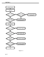
Perform troubleshooting according to the malfunction diagnosis flowchart (Figure 4-1-1). If an
“image defect” is found, the defective part must be located and rectified by the following proce-
dure.
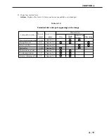
Table 4-2-1
II-1.
Light
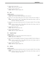
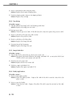
<Possible causes>
1) Improperly adjusted image density
Action:
Adjust the image density by operating the external device.
2) Open the top cover and remove the EP-22 cartridge while printing. Open the drum protec-
tive shield of the cartridge and check the toner image on the photosensitive drum surface.
If the toner image has not been transferred to the paper properly, go to step 3). If the toner
image on the drum is faint, go to step 6).
Do not open the drum protective shield for more than 10 seconds.
3) Deformation or deterioration of the transfer charging roller.
Action:
Replace the transfer charging roller.
4) Poor contact in the transfer charging roller contact on the engine controller PCB and the
transfer charging roller shaft contact.
Action:
Clean the contacts if dirty. If the problem still remains after cleaning, or parts are
deformed or damaged, replace them.
CHAPTER 4
4 - 6
2-1 Light
2-2 Dark
2-3 Completely blank
2-4 All black
2-5 Dirt on back of paper
2-6 Dirt
2-7 Black vertical lines
2-8 White vertical lines
2-9 Black horizontal lines
2-10 White horizontal lines
2-11 Blank spots
2-12 Poor fixing
2-13 Image distortion
2-14 Faulty registration
Defects
Additional explanation
Output very light image.
Output very dark image.
Output no image.
Output all black paper.
Output dirt on the back of the paper.
Output dirt on surface of the paper.
Output black vertical lines.
Output white vertical lines.
Output black horizontal lines.
Output white horizental lines.
Output image with blank spots.
Output image with poorly fixed toner.
Output distored image.
Gap between the leading edges of the paper and the image.
Image defects
Содержание LBP-800
Страница 8: ......
Страница 68: ......
Страница 74: ......
Страница 110: ......
Страница 127: ...VI MOTOR SOLENOID A Locations M001 Main motor SL001 Pick up solenoid Figure 3 6 1 CHAPTER 3 3 17 SL001 M001 ...
Страница 129: ...VII PCBs A Locations Interface controller PCB Engine controller PCB Display PCB Figure 3 7 1 CHAPTER 3 3 19 ...
Страница 134: ......
Страница 136: ......
Страница 164: ......
Страница 165: ...APPENDIX I GENERAL TIMING CHART A 1 II GENERAL CIRCUIT DIAGRAM A 3 III LIST OF SIGNALS A 5 IV MESSAGES TABLE A 7 ...
Страница 166: ......
Страница 168: ......
Страница 178: ...The printing paper contains 70 waste paper PRINTED IN JAPAN IMPRIME AU JAPON 0899AB0 50 CANON INC ...


