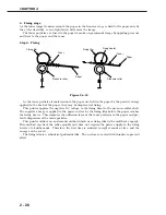
In the specified period of time after the paper reaches the paper top sensor (PS002), the
engine controller sends the /BD signal to the interface controller. The interface controller sends
the VIDEO signal to the engine controller based on the /BD signal to form an image on the pho-
tosensitive drum. As a result, the leading edge of the image matches with the leading edge of
the paper. The paper is transferred to the face-up delivery slot or to the face-down tray through
the transfer unit, separation unit, fixing unit, and delivery unit.
When the delivery switching lever is up, the paper is delivered to the face-down tray, and
when the lever is down, to the face-up delivery slot.
There are two photointerrupters (PS002 and PS201) in the paper path to detect paper.
If the paper does not reach or pass each sensor within the specified period of time, the CPU
on the engine controller assumes paper jam has occurred and notifies the interface controller of
the jam.
Since this printer loads paper from the top, a few papers or a curled paper may not be picked
up. The printer has a pick-up retry function. If the paper top sensor cannot detect the leading
edge of paper within the specified period of time after the pick-up solenoid turns ON, the print-
er does not assume it as a jam and tries to pick up the paper again. The printer performs this
pick-up retry function up to twice. If the paper top sensor cannot detect the leading edge of the
paper within the specified period of time in the third trial, the printer assumes that a paper pick-
up delay jam has occurred.
Note:
Initial rotation ready
The state in which the main motor is rotating and the fixing unit temperature has
reached the specified value in a specified period of time after the start of main motor
rotation.
CHAPTER 2
2 - 31
Содержание LBP-800
Страница 8: ......
Страница 68: ......
Страница 74: ......
Страница 110: ......
Страница 127: ...VI MOTOR SOLENOID A Locations M001 Main motor SL001 Pick up solenoid Figure 3 6 1 CHAPTER 3 3 17 SL001 M001 ...
Страница 129: ...VII PCBs A Locations Interface controller PCB Engine controller PCB Display PCB Figure 3 7 1 CHAPTER 3 3 19 ...
Страница 134: ......
Страница 136: ......
Страница 164: ......
Страница 165: ...APPENDIX I GENERAL TIMING CHART A 1 II GENERAL CIRCUIT DIAGRAM A 3 III LIST OF SIGNALS A 5 IV MESSAGES TABLE A 7 ...
Страница 166: ......
Страница 168: ......
Страница 178: ...The printing paper contains 70 waste paper PRINTED IN JAPAN IMPRIME AU JAPON 0899AB0 50 CANON INC ...


