


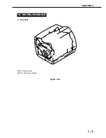


C. Engine controller PCB
1) Remove the external covers.
2) Performing the interface controller PCB
removal procedures 1) through 3) on
page 3-20, remove the interface con-
troller unit.
3) Remove the screw on the left of the
printer, and disconnect the connector.
➀
Screw
➁
Connector
Figure 3-7-5
4) Remove the screw on the right of the
printer, and disconnect the connector.
➀
Screw
➁
Connector
Figure 3-7-6
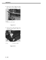
5) Remove the two screws on the back of
the printer, and disconnect the two con-
nectors.
➀
Screws
➁
Connectors
Figure 3-7-7
6) Remove the 2 screws. Pull out the
engine controller unit toward you to
disconnect the 2 connectors on the
engine controller PCB. Remove the
engine controller unit.
➀
Screws
➁
Engine controller unit
Figure 3-7-8
CHAPTER 3
3 - 21
➁
➀
➁
➀
➁
➀
➀
➁
Содержание LBP-800
Страница 8: ......
Страница 68: ......
Страница 74: ......
Страница 110: ......
Страница 127: ...VI MOTOR SOLENOID A Locations M001 Main motor SL001 Pick up solenoid Figure 3 6 1 CHAPTER 3 3 17 SL001 M001 ...
Страница 129: ...VII PCBs A Locations Interface controller PCB Engine controller PCB Display PCB Figure 3 7 1 CHAPTER 3 3 19 ...
Страница 134: ......
Страница 136: ......
Страница 164: ......
Страница 165: ...APPENDIX I GENERAL TIMING CHART A 1 II GENERAL CIRCUIT DIAGRAM A 3 III LIST OF SIGNALS A 5 IV MESSAGES TABLE A 7 ...
Страница 166: ......
Страница 168: ......
Страница 178: ...The printing paper contains 70 waste paper PRINTED IN JAPAN IMPRIME AU JAPON 0899AB0 50 CANON INC ...


