2 - 18
COPYRIGHT © 2003 CANON ELECTRONICS INC. CANON DR-6080/9080C REV.0 SEPT. 2003
CHAPTER 2 FUNCTIONS & OPERATION
5 Skew Correction Mechanism
The skew correction (deskew) uses the front
registration sensors and the registration rollers.
Skew is detected by the front registration sensor
and then is corrected by the registration rollers.
Fig. 2-309 shows the arrangement of the front
registration sensors and Fig. 2-310 shows the
skew correction mechanism.
As shown in Fig. 2-309, the front registration
sensors consist of the left sensor (L) and the right
sensor (R), and are mounted in front of the
registration roller. If no skewing occurs, there is
no difference in the timing for both sensors
detecting the document. However, if the
document is skewed, one of the sensors detects
the document earlier and there is a difference in
the timing of detecting the document. As the
skew amount is increased, the difference is also
increased. The difference affects the time of the
skew correction performed by the registration
roller, and an increased difference will prolong
the skew correction time.
The time taken from the time both sensors
detect the document together untill the
registration roller begins to rotate is the time
required for the skew correction.
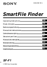
As shown in Fig. 2-310, the skew correction
is performed at the registration roller area. When
the feed roller feeds the document in the feeding
direction, either the right or left front end of the
document runs into the registration roller. Since
the registration roller remains stopped, the
document is turned on the fore-end of the
document run into the registration roller so that
the skew is corrected. (Refer to Fig. 2-310-a)
When the skew correction is performed after
both sensors detect the document together, the
registration roller begins to rotate and the
document is fed without being skewed. (Refer to
2-310-b)
Feed direction
Document
Front
registration
R sensor
Front
registration
L sensor
Registration roller
Fig. 2-309
Feed direction
Document
Turns
this way
Registration roller (stopped)
Registration roller (rotating)
a.
b.
Fig. 2-310
Содержание ImageFormula DR-9080C
Страница 4: ......
Страница 22: ......
Страница 24: ...3 0 COPYRIGHT 2001 CANON ELECTRONICS INC CANON DR 5060F REJULYY 2001 PRINTED IN JAPAN IMPRIME AU JAPON...
Страница 82: ...3 0 COPYRIGHT 2001 CANON ELECTRONICS INC CANON DR 5060F REJULYY 2001 PRINTED IN JAPAN IMPRIME AU JAPON...
Страница 128: ...3 0 COPYRIGHT 2001 CANON ELECTRONICS INC CANON DR 5060F REVJULY 2001 PRINTED IN JAPAN IMPRIME AU JAPON...
Страница 150: ...3 0 COPYRIGHT 2001 CANON ELECTRONICS INC CANON DR 5060F REVJULY 2001 PRINTED IN JAPAN IMPRIME AU JAPON...
Страница 180: ...3 0 COPYRIGHT 2001 CANON ELECTRONICS INC CANON DR 5060F REVJULY 2001 PRINTED IN JAPAN IMPRIME AU JAPON...
Страница 182: ......
Страница 188: ...1003N0 0 1...
Страница 195: ...COPYRIGHT 2003 CANON ELECTRONICS INC CANON DR 6080 9080C FIRST EDITION OCT 2003 vii...
Страница 236: ......
Страница 240: ......
Страница 242: ...ix 1003N0 0 0...
Страница 284: ...38 Chapter 3 Software Closing CapturePerfect 1 Select Exit from the File menu...
Страница 308: ......
Страница 352: ...1 Imprinter for DR 6080 9080C Installation Procedure IMS Product Planning Dept...
Страница 354: ...3 2 Remove the rear cover 6 screws Note The rear cover of mass production model will be painted Remove these screws x6...
Страница 355: ...4 3 Remove the left cover 4 screws Remove these screws x4...
Страница 357: ...6 5 Open the upper unit and remove the screws x6 of right and left sides Remove these screws x6...
Страница 358: ...7 6 Insert the IP drain pad unit to the hole of left side of the main body in the proper direction...
Страница 359: ...8 7 Insert it firmly to the back and fix it with 1 screw M3x6...
Страница 360: ...9 8 Remove the cable from the cable clamp of right side of main body s interior to avoid becoming an obstacle later...
Страница 361: ...10 9 Insert the IP shaft to the hole of left side of main body s interior Insert the one that a tip is long Long...
Страница 362: ...11 10 Insert the tip of rest one of the IP shaft to the hole of right side of main body s interior Short...
Страница 363: ...12 11 Fit the retaining ring to left side of the IP shaft and fix it not to move Retaining ring...
Страница 365: ...14 13 Insert the connector of the imprinter carriage to the following position of 80 sub PCB of main body...
Страница 366: ...15 14 Replace the cable to cable clamp and the document eject cover to the original position...