Chapter 6
6-11
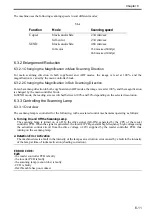
The machine uses the following scanning speeds to suit different modes;
T-6-4
6.3.2 Enlargement/Reduction
6.3.2.1 Changing the Magnification in Main Scanning Direction
For main scanning direction in both copyboard and ADF modes, the image is read at 100%, and the
magnification is varied by the main controller block.
6.3.2.2 Changing the Magnification in Sub Scanning Direction
For sub scanning direction in both copyboard and ADF modes, the image is read at 100%, and the magnification
is changed by the main controller block.
In SEND mode, the reading size is switched between 100% and 50% depending on the selected resolution.
6.3.3 Controlling the Scanning Lamp
6.3.3.1 Overview
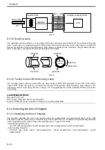
The scanning lamp is controlled for the following, with associated control mechanisms operating as follows:
1. Turning On and Off the Scanning Lamp
The scanning lamp is turned on or off by the drive signal (XE-ON) generated by the CPU of the reader
controller PCB. When the signal is generated, the inverter PCB generates high-frequency high voltage using
the activation control circuit from the drive voltage (+24V) supplied by the reader controller PCB, thus
turning on the scanning lamp.
2. Detection Error Activation
The machine detects a fault in the intensity of the lamp as an activation error caused by a fault in the intensity
of the lamp at time of initial activation (shading correction).
ERROR CODE:
E225
- the reader controller PCB is faulty
- the inverter PCB is faulty
- the scanning lamp (xenon tube) is faulty
- CCD is faulty
- flexible cable has poor contact
Function
Mode
Scanning speed
Copier
black-and-white
234 mm/sec
full-color
234 mm/sec
SEND
black-and-white
468 mm/sec
full-color
234 mm/sec(600dpi)
468 mm/sec(300dpi)
Содержание Color imageRUNNER C5180 Series
Страница 22: ...Chapter 1 INTRODUCTION...
Страница 64: ...Chapter 2 INSTALLATION...
Страница 110: ...Chapter 3 BASIC OPERATION...
Страница 119: ...Chapter 4 BASIC OPERATIONS AS A PRINTER...
Страница 129: ...Chapter 5 MAIN CONTROLLER...
Страница 132: ...Chapter 5 5 2 F 5 1 A Reader Unit B DC controller Circuit Board C Printer Unit A B C HDD 1 2 3 3 4 5 6 7 8 9...
Страница 138: ...Chapter 5 5 8 F 5 8 CPU HDD ROM access to the program at time of execution...
Страница 165: ...Chapter 6 ORIGINAL EXPOSURE SYSTEM...
Страница 209: ...Chapter 7 IMAGE PROCESSING SYSTEM...
Страница 210: ...Contents Contents 7 1 Digital Image Processing 7 1 7 1 1 Overview 7 1 7 1 2 Shading Correction 7 1...
Страница 212: ...Chapter LASER EXPOSURE 8...
Страница 239: ...Chapter 9 IMAGE FORMATION...
Страница 324: ...Chapter 10 PICKUP FEEDING SYSTEM...
Страница 355: ...Chapter 10 10 28 F 10 30 F 10 31 9 1 2 3 4 5 1 2 3 4 5 10 thereafter repeats 7 through 10 11 1 2 3 4 5 12 1 2 3 4 5...
Страница 358: ...Chapter 10 10 31 F 10 36 F 10 37 5 1 2 6 1 2 in wait for re pickup point of reversal 9 1 2 3 10 1 2 3...
Страница 435: ...Chapter 11 FIXING SYSTEM...
Страница 460: ...Chapter 11 11 23 F 11 13 SEN3 SEN2 SEN1 SEN2 SEN3 SEN1 SEN2 SEN3 SEN1...
Страница 491: ...Chapter 12 EXTERNALS CONTROLS...
Страница 498: ...Chapter 12 12 5 F 12 2 FM1 FM7 FM9 FM2 FM13 FM14 FM12 FM11 FM10 FM5 FM3 FM4 FM8 FM6...
Страница 512: ...Chapter 12 12 19 2 Remove the check mark from SNMP Status Enabled F 12 10...
Страница 553: ...Chapter 13 MEAP...
Страница 557: ...Chapter 14 RDS...
Страница 569: ...Chapter 15 MAINTENANCE INSPECTION...
Страница 578: ...Chapter 16 STANDARDS ADJUSTMENTS...
Страница 597: ...Chapter 17 CORRECTING FAULTY IMAGES...
Страница 612: ...Chapter 17 17 14 F 17 7 PLG1 ELCB1 SP1 H4 H3 H2 H1 H1 H2 LA1...
Страница 617: ...Chapter 18 SELF DIAGNOSIS...
Страница 644: ...Chapter 19 SERVICE MODE...
Страница 778: ...Chapter 20 UPGRADING...
Страница 823: ...Chapter 21 SERVICE TOOLS...
Страница 824: ...Contents Contents 21 1 Service Tools 21 1 21 1 1 Special Tools 21 1 21 1 2 Solvents and Oils 21 2...
Страница 828: ...APPENDIX...
Страница 851: ......


