Chapter 19
19-80
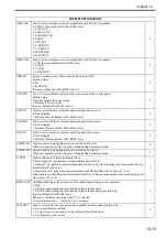
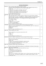
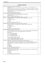
TMC-SLCT Used to select coefficient used in error diffusion process.
0: Low granularity/low dot stability for Y/M/C/Bk
1: Y/M/C -> Low granularity, low dot stability, Bk -> high granularity, low dot stability [Factory
default/After RAM clear]
2: High granularity/low dot stability for Y/M/C/Bk
2
CAL-SW
Used to switch condition for performing calibration control.
Whenever possible, avoid using this setting during normal operation.
2
CLN-PTH
Sets threshold value (number of sheets) for starting drum cleaning sequence.
Whenever possible, avoid using this setting during normal operation.
2
CLN-VTH
Sets threshold value (image density) for starting drum cleaning sequence.
Whenever possible, avoid using this setting during normal operation.
2
DEVL-VTH Sets threshold value (video count) for starting toner forcible consumption sequence.
Whenever possible, avoid using this setting during normal operation.
2
FTPTXPN
Used to specify port (FTP) number to send to.
0 to 65535 (16-bit value) [Factory default/After RAM clear: 21]
2
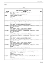
PRNT-ORD Used to switch order of output to side tray.
Whenever possible, avoid using this setting during normal operation.
2
INTPPR-1
Sets interval (number of sheets) for performing image stabilization control (adjustment set 1) between
sheets.
0.50 to 1000 [Factory default/After RAM clear: 100]
2
DWNSQ-
SW
Used to improve tray loading during one-sided continuous printing.
Whenever possible, avoid using this setting during normal operation.
2
PRN-FLG
Used to select area flag for PDL images.
Whenever possible, avoid using this setting during normal operation.
2
SCN-FLG
Used to select area flag for copy images.
Whenever possible, avoid using this setting during normal operation.
2
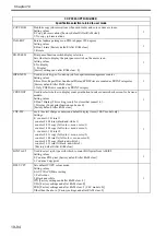
T-LW-LVL
Used to switch timing for display of remaining toner volume warning message.
Whenever possible, avoid using this setting during normal operation.
2
DVTGT-Y/
M/C/K
developer concentration target value offsets
Whenever possible, avoid using these settings during normal operation.
2
NWERR-
SW
Used to select whether to display network error messages.
0: Don't display
1: Display [Factory default/After RAM clear]
2
FX-SPD
Used to adjust fixing roller speed.
-2 to 2
[Factory default/After RAM clear: 0]
Increasing the setting value increases the fixing roller's speed (in 0.8% increments).
Setting this value automatically increases the operation speed of the paper delivery vertical path motor
(the speed increases by the same ratio as the speed of the fixing roller).
2
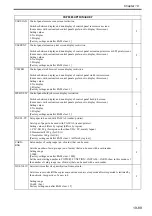
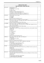
EX-PS-SP
Used to adjust paper delivery vertical path motor speed.
-2 to 2
[Factory default/After RAM clear: 0]
2
FX-N-ROT
Used to turn fixing motor idle after warmup ON/OFF.
0: ON (idle) [Factory default/After RAM clear]
1: OFF (don't idle)
Setting this value to 1 increases the amount of paper curl, and reduces the capacity for the load on the
paper delivery tray.
2
FX-SUB
Sets the fixing sub-heater's lighting ratio.
0: Normal [Factory default/After RAM clear]
1: Level 1
2: Level 2
Increasing this setting value decreases the lighting ratio (shortens the lighting time).
2
COPIER>OPTION>BODY
Содержание Color imageRUNNER C5180 Series
Страница 22: ...Chapter 1 INTRODUCTION...
Страница 64: ...Chapter 2 INSTALLATION...
Страница 110: ...Chapter 3 BASIC OPERATION...
Страница 119: ...Chapter 4 BASIC OPERATIONS AS A PRINTER...
Страница 129: ...Chapter 5 MAIN CONTROLLER...
Страница 132: ...Chapter 5 5 2 F 5 1 A Reader Unit B DC controller Circuit Board C Printer Unit A B C HDD 1 2 3 3 4 5 6 7 8 9...
Страница 138: ...Chapter 5 5 8 F 5 8 CPU HDD ROM access to the program at time of execution...
Страница 165: ...Chapter 6 ORIGINAL EXPOSURE SYSTEM...
Страница 209: ...Chapter 7 IMAGE PROCESSING SYSTEM...
Страница 210: ...Contents Contents 7 1 Digital Image Processing 7 1 7 1 1 Overview 7 1 7 1 2 Shading Correction 7 1...
Страница 212: ...Chapter LASER EXPOSURE 8...
Страница 239: ...Chapter 9 IMAGE FORMATION...
Страница 324: ...Chapter 10 PICKUP FEEDING SYSTEM...
Страница 355: ...Chapter 10 10 28 F 10 30 F 10 31 9 1 2 3 4 5 1 2 3 4 5 10 thereafter repeats 7 through 10 11 1 2 3 4 5 12 1 2 3 4 5...
Страница 358: ...Chapter 10 10 31 F 10 36 F 10 37 5 1 2 6 1 2 in wait for re pickup point of reversal 9 1 2 3 10 1 2 3...
Страница 435: ...Chapter 11 FIXING SYSTEM...
Страница 460: ...Chapter 11 11 23 F 11 13 SEN3 SEN2 SEN1 SEN2 SEN3 SEN1 SEN2 SEN3 SEN1...
Страница 491: ...Chapter 12 EXTERNALS CONTROLS...
Страница 498: ...Chapter 12 12 5 F 12 2 FM1 FM7 FM9 FM2 FM13 FM14 FM12 FM11 FM10 FM5 FM3 FM4 FM8 FM6...
Страница 512: ...Chapter 12 12 19 2 Remove the check mark from SNMP Status Enabled F 12 10...
Страница 553: ...Chapter 13 MEAP...
Страница 557: ...Chapter 14 RDS...
Страница 569: ...Chapter 15 MAINTENANCE INSPECTION...
Страница 578: ...Chapter 16 STANDARDS ADJUSTMENTS...
Страница 597: ...Chapter 17 CORRECTING FAULTY IMAGES...
Страница 612: ...Chapter 17 17 14 F 17 7 PLG1 ELCB1 SP1 H4 H3 H2 H1 H1 H2 LA1...
Страница 617: ...Chapter 18 SELF DIAGNOSIS...
Страница 644: ...Chapter 19 SERVICE MODE...
Страница 778: ...Chapter 20 UPGRADING...
Страница 823: ...Chapter 21 SERVICE TOOLS...
Страница 824: ...Contents Contents 21 1 Service Tools 21 1 21 1 1 Special Tools 21 1 21 1 2 Solvents and Oils 21 2...
Страница 828: ...APPENDIX...
Страница 851: ......


