Chapter 2
2-24
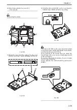
11) Remove the screw [1], and disconnect the power
cord [2].
F-2-67
12) Fix the power cord face plate in place using the
screw [1] removed in step 11).
F-2-68
13) Fit the power cord mount, DC power supply unit,
IH power supply unit, and covers in reverse order.
2.2.10 Connecting the Power Cord
1) Connect the one side of the power cable to the
inlet of the main body, and connect the other side
to the outlet.
2.2.11 Adjustment of Fixing Assembly
1. Turning Off the Host Machine
How to Turn Off the Host Machine
When turning off the host machine, be sure to go
through the following steps to protect the hard disk:
1) Hold down the control panel power switch for 3
sec or more.
2) Operate as instructed in the shut-down sequence
screen (so that the main power switch will go off
automatically).
3) Disconnect the power cable (for the power outlet).
2. Adjustment of Fixing Assembly
1)
Enter the Service mode.
Select COPIER > FUNCTION > FIXING > FX-
UHP-S > OK
2) Check that 'FX-UHP-S is OK (It will take for
about 5 minutes.)
3)
Enter the Service mode.
Select COPIER > FUNCTION > FIXING > FX-
LHP-S > OK
4) Check that 'FX- LHP -S is OK (It will take for
about 5 minutes.)
2.2.12 Checking the Image Margin
1) Place the test chart on the copyboard glass, make
a copy by picking up paper from the cassette (1,2),
and check the image.
(When the two-cassette pedestal is installed, pick
up paper from the cassette 3, 4 and check the
image.)
- Check to be sure that there is no unusual sound.
- Check the image quality every standard
magnification.
- Check to be sure that the operation for specified
number of sheets is performed correctly.
- Check to be sure that the image on the paper
picked up from each cassette meets the
specification.
Specification values should be as follows.
If the figure is out of the spec, see 'Adjustment of
Left Margin of Image' and 'Adjustment of Margin
along Leading Edge of Image'.
- Standard value for the left margin of image: L2
= 2.0 +/-1.5 mm
- Standard value for the margin along leading
edge of image: L1 = 2.5 +/-1.5 mm
After the adjustment of left margin of image /
margin along leading edge of image, if the margin
is out of specification, be sure to make an
adjustment of the image area (non-image area).
2.2.13 Adjustment of Left Margin of
Image
- Check to be sure that the margin of the side of
the paper is L2 = 2.0 +/-1.5 mm when the paper is
picked up from each cassette.
1) Pull out the cassette 1 and 2.
(Open the cassette 3 and 4 too if the two-cassette
pedestal is installed.)
2) Open the pickup vertical path cover [1] and pull
out the manual feed unit [2].
[1]
[2]
[1]
[2]
Содержание Color imageRUNNER C5180 Series
Страница 22: ...Chapter 1 INTRODUCTION...
Страница 64: ...Chapter 2 INSTALLATION...
Страница 110: ...Chapter 3 BASIC OPERATION...
Страница 119: ...Chapter 4 BASIC OPERATIONS AS A PRINTER...
Страница 129: ...Chapter 5 MAIN CONTROLLER...
Страница 132: ...Chapter 5 5 2 F 5 1 A Reader Unit B DC controller Circuit Board C Printer Unit A B C HDD 1 2 3 3 4 5 6 7 8 9...
Страница 138: ...Chapter 5 5 8 F 5 8 CPU HDD ROM access to the program at time of execution...
Страница 165: ...Chapter 6 ORIGINAL EXPOSURE SYSTEM...
Страница 209: ...Chapter 7 IMAGE PROCESSING SYSTEM...
Страница 210: ...Contents Contents 7 1 Digital Image Processing 7 1 7 1 1 Overview 7 1 7 1 2 Shading Correction 7 1...
Страница 212: ...Chapter LASER EXPOSURE 8...
Страница 239: ...Chapter 9 IMAGE FORMATION...
Страница 324: ...Chapter 10 PICKUP FEEDING SYSTEM...
Страница 355: ...Chapter 10 10 28 F 10 30 F 10 31 9 1 2 3 4 5 1 2 3 4 5 10 thereafter repeats 7 through 10 11 1 2 3 4 5 12 1 2 3 4 5...
Страница 358: ...Chapter 10 10 31 F 10 36 F 10 37 5 1 2 6 1 2 in wait for re pickup point of reversal 9 1 2 3 10 1 2 3...
Страница 435: ...Chapter 11 FIXING SYSTEM...
Страница 460: ...Chapter 11 11 23 F 11 13 SEN3 SEN2 SEN1 SEN2 SEN3 SEN1 SEN2 SEN3 SEN1...
Страница 491: ...Chapter 12 EXTERNALS CONTROLS...
Страница 498: ...Chapter 12 12 5 F 12 2 FM1 FM7 FM9 FM2 FM13 FM14 FM12 FM11 FM10 FM5 FM3 FM4 FM8 FM6...
Страница 512: ...Chapter 12 12 19 2 Remove the check mark from SNMP Status Enabled F 12 10...
Страница 553: ...Chapter 13 MEAP...
Страница 557: ...Chapter 14 RDS...
Страница 569: ...Chapter 15 MAINTENANCE INSPECTION...
Страница 578: ...Chapter 16 STANDARDS ADJUSTMENTS...
Страница 597: ...Chapter 17 CORRECTING FAULTY IMAGES...
Страница 612: ...Chapter 17 17 14 F 17 7 PLG1 ELCB1 SP1 H4 H3 H2 H1 H1 H2 LA1...
Страница 617: ...Chapter 18 SELF DIAGNOSIS...
Страница 644: ...Chapter 19 SERVICE MODE...
Страница 778: ...Chapter 20 UPGRADING...
Страница 823: ...Chapter 21 SERVICE TOOLS...
Страница 824: ...Contents Contents 21 1 Service Tools 21 1 21 1 1 Special Tools 21 1 21 1 2 Solvents and Oils 21 2...
Страница 828: ...APPENDIX...
Страница 851: ......


