background image

Sep 8 2010

Service Manual

LBP6000/6018/3010/3100/3150 Series


Содержание LBP6000 Series

Страница 1: ...Sep 8 2010 Service Manual LBP6000 6018 3010 3100 3150 Series...

Страница 2: ......

Страница 3: ...need arises In the event of major changes in the contents of this manual over a long or short period Canon will issue a new edition of this manual The following paragraph does not apply to any countri...

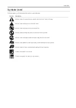
Страница 4: ...uiring care to avoid combustion fire Indicates an item prohibiting disassembly to avoid electric shocks or problems Indicates an item requiring disconnection of the power plug from the electric outlet...

Страница 5: ...ed to indicate Low The voltage value how ever differs from circuit to circuit In addition the asterisk as in DRMD indicates that the DRMD signal goes on when 0 In practically all cases the internal me...

Страница 6: ......

Страница 7: ...10 1 5 8 Safety of Toner 1 10 1 5 9 Handling the Laser Unit 1 11 1 5 10 Points to Note at Disassembly Assembly Work 1 11 Chapter 2 TECHNICAL REFERENCE 2 1 Functional Configuration 2 1 2 1 1 Outline 2...

Страница 8: ...loping Bias 2 20 2 4 2 8 Generating Transfer Bias 2 20 2 4 3 Toner Cartridge 2 20 2 4 3 1 Toner Level Detection 2 20 2 4 3 2 Toner Cartridge Absence Presence Detection 2 20 2 4 3 3 Toner Level Detecti...

Страница 9: ...the Front Cover 3 6 3 1 5 4 Removing the Front Cover 3 6 3 1 6 Delivery Tray 3 7 3 1 6 1 Removing the Delivery Auxiliary Tray 3 7 3 1 7 Pickup Tray 3 7 3 1 7 1 Preparation for Removing the Pickup Tray...

Страница 10: ...aration for Removing the Pickup Unit 3 28 3 4 1 2 Removing the Pickup Unit 3 28 3 4 1 3 Before Removing the Pickup Unit 3 29 3 4 1 4 Removing the Pickup Unit 3 29 3 4 2 Cassette Pickup Roller 3 31 3 4...

Страница 11: ...TMENT 5 2 5 2 1 Test Print 5 2 5 2 1 1 Test Print Function 5 2 5 2 2 Mechanical Adjustment 5 2 5 2 2 1 Nip width pressure from the pressure roller specifications 5 2 5 3 SERVICE TOOLS 5 3 5 3 1 Standa...

Страница 12: ...Contents...

Страница 13: ...Chapter 1 PRODUCT DESCRIPTION...

Страница 14: ......

Страница 15: ...ss Section 1 7 1 4 Using the Machine 1 8 1 4 1 Control Panel 1 8 1 4 2 Control Panel 1 8 1 5 Safety 1 8 1 5 1 Safety of Laser Light 1 8 1 5 2 CDRH Regulations 1 9 1 5 3 Safety of Toner 1 9 1 5 4 Handl...

Страница 16: ......

Страница 17: ...enance jam removal replacing the cartridge can be performed by ac cessing one point of the delivery tray MEMO 1 For this equipment the 16 ppm model and 14 ppm model are available according to the sale...

Страница 18: ...the conventional gear drive method See MEMO 2 4 Improved Usability In this equipment the power switch is situated at the front of the host machine and maintenance jam removal replacing the cartridge c...

Страница 19: ...mm in width 127 to 355 6 mm in length Multi purpose paper size A4 B5 A5 LGL LTR Executive Envelope DL COM10 C5 Monarch user defined paper 76 2 to 215 9 mm in width 127 to 355 6 mm in length Pickup tr...

Страница 20: ...r 76 2 to 215 9 mm in width 188 to 355 6 mm in length Pickup tray paper type plain paper 60 to 105 g m2 heavy paper 106 to 163 g m2 transparency label sheet postcard envelope Pickup tray paper capacit...

Страница 21: ...tch 2 Delivery auxiliary tray 3 Delivery tray 4 Manual feed tray paper guide 5 Manual feed tray 6 Tray cover 7 Pickup tray 8 Small size paper guide 9 Rear paper guide 10 Manual feed tray Paper guide 1...

Страница 22: ...1 Fixing unit 2 Pressure roller 3 Delivery roller 4 Fixing film unit 5 Laser scanner unit 6 Manual feed tray 7 Pickup tray 8 Photosensitive drum 9 Pickup roller 10 separation pad 11 Feed roller 12 Tr...

Страница 23: ...y 4 Output Tray 5 Paper Guide 6 Rear Cover 7 USB Connector 8 Power Socket 1 Fixing unit 2 Pressure roller 3 Delivery roller 4 Fixing film unit 5 Laser scanner unit 6 Pickup tray 7 Photosensitive drum...

Страница 24: ...ing pickup of paper or jam removal restarts printing 1 4 2 Control Panel 0025 1124 LBP6000 LBP6000B F 1 7 1 Power lamp green Lighting Indicates that the power of the host machine is turned on Not ligh...

Страница 25: ...nd after August 1 1976 and prohibit the sale of laser products without certification The following is a label used to certify compliance with the CDRH regulations and all laser products to be sold in...

Страница 26: ...er is free of laser related hazards as long as the machine is being used for its intended purposes The following warnings are given to comply with Safety Principles EN60950 Laserstrahlen k nnen f r de...

Страница 27: ...yes The unit cannot be adjusted in the field The following label is attached to the cover of the unit F 1 12 F 1 13 1 5 10 Points to Note at Disassembly Assembly Work 0025 1134 LBP6000 LBP6000B Be sur...

Страница 28: ......

Страница 29: ...Chapter 2 TECHNICAL REFERENCE...

Страница 30: ......

Страница 31: ...tor Fault Detection 2 9 2 4 IMAGE FORMATION SYSTEM 2 10 2 4 1 Overview Configuration 2 10 2 4 1 1 Overview 2 10 2 4 1 2 Print Process 2 10 2 4 1 3 Static Latent Image Formation Block 2 11 2 4 1 4 Deve...

Страница 32: ...27 2 6 1 1 2 Low voltage power circuit 2 28 2 6 1 2 Protective Functions 2 29 2 6 1 2 1 Power protective function 2 29 2 6 1 2 2 Safety function 2 30 2 6 1 2 3 Power protective function 2 30 2 6 1 2...

Страница 33: ...externals auxiliary control system F 2 2 2 2 Basic Sequence 2 2 1 Basic Sequence of Operation 0019 4168 LBP3100 LBP3010B The engine controller controls the operation sequence The following table prov...

Страница 34: ...keep the printer ready to print INTR initial rotation From the input of the print command from the main controller until the pick up solenoid is turned ON To stabilize the photosensitive drum sensitiv...

Страница 35: ...oller rotates the Four faced mirror causing the Scanner motor to rotate 2 When the Scanner motor starts to rotate the Engine controller emits the laser forcibly using the Laser control signal causing...

Страница 36: ...r motor 3 The Engine controller controls to keep a constant speed of rotation of the Scanner motor using the Scanner motor speed control signal 4 After the rotation speed of the Scanner motor reaches...

Страница 37: ...etails of control procedure 1 The engine controller controls the laser control signal during unblanking to emit the laser diode LD forcibly 2 The BD PCB exists on the scanning route of the laser beam...

Страница 38: ...well as the video signal VD0 VD0 for image formation The laser driver IC executes laser control according to the combination of the CNT0 CNT1 signals The following is the combination of the laser cont...

Страница 39: ...ol signal enters LD forced OFF mode the LD is forcibly turned off The laser driver saves the adjusted laser intensity to the capacitor C1 2 3 3 2 Auto Power Control APC 0025 1143 LBP6000 LBP6000B This...

Страница 40: ...nto either of the following status the engine controller judges it as a fault in the laser scanner unit system and notices the status of fault to the main controller The operations of the host machine...

Страница 41: ...5 1149 LBP6000 LBP6000B This is the detection of faults in the laser scanner unit When the laser unit scanner unit falls into either of the following status the engine controller judges it as a fault...

Страница 42: ...0 LBP3010B This explains the basic process of the operations that a printer executes for image formation The print process of this equipment is divided largely into 5 blocks 7 steps Toner images are f...

Страница 43: ...the primary charging roller directly to the photosensitive drum DC bias is applied to the primary charging roller to maintain an even potential on the surface of the photosensitive drum F 2 12 Step 2...

Страница 44: ...laser beam has higher potential than the developing cylinder the potential difference between the drum surface and the cylinder enables the toner to jump on the drum surface and makes them visible ima...

Страница 45: ...o fix toner images to the papers Step 6 Fixing This step employs on demand fixing that fixes toner images transferred to papers on the papers F 2 17 2 4 1 7 Drum Cleaning Block 0019 5437 LBP3100 LBP30...

Страница 46: ...ions of image formation F 2 19 2 4 1 9 Print Process 0025 1153 LBP6000 LBP6000B This explains the basic process of the operations that a printer executes for image formation The print process of this...

Страница 47: ...xposed The images on the drum with negative charge are called static latent images because human eyes cannot detect them F 2 21 Step 1 Primary charging For preparation of latent image formation the su...

Страница 48: ...velops the images The toner developer used for this equipment is a one component toner that comprises magnetic body and resin etc Step 3 Development Toner is affixed to static latent images on the sur...

Страница 49: ...bias is applied to the static eliminator according to the elasticity of papers to separate the papers from the photosensitive drum The static eliminator is used to stabilize the paper feed system pre...

Страница 50: ...is cleaned F 2 28 2 4 2 High Voltage Control 2 4 2 1 Overview 0019 5443 LBP3100 LBP3010B This circuit is comprised of the circuits that apply biases to the primary charging roller developing cylinder...

Страница 51: ...high voltage power supply circuit The DC positive bias is output at the time of toner transfer and the DC negative bias at the time of cleaning the photosensitive drum The high voltage power supply c...

Страница 52: ...o papers There are two types of bias DC positive bias and DC negative bias and generated by the transfer high voltage generating circuit in the high voltage power supply circuit The DC positive bias i...

Страница 53: ...ing H it is judged that the Toner cartridge is present F 2 31 The leading edge sensor performs both this detection and paper feed detection Therefore the engine controller cannot make a judgment of To...

Страница 54: ...S801 When the output result of PS801 is L it is judged that the Toner cartridge is absent If being H it is judged that the Toner cartridge is present F 2 32 The leading edge sensor performs both this...

Страница 55: ...sensor PS702 Fixing delivery sensor PS801 Paper leading edge sensor M1 Main motor SL1 Pickup solenoid 2 5 1 2 Overview 0025 1168 LBP6000 LBP6000B The pickup feeding system executes pickup and feeding...

Страница 56: ...view 0019 5975 LBP3100 LBP3010B The following sensors are installed to detect absence presence of papers and whether papers are correctly fed Paper width sensor PS701 Fixing delivery sensor PS702 Pape...

Страница 57: ...P6000 LBP6000B The following sensors are installed to detect absence presence of papers and whether papers are correctly fed Paper width sensor PS701 Fixing delivery sensor PS702 Paper leading edge se...

Страница 58: ...PS801 2 5 2 3 4 Delivery Stationary Jam 0025 1172 LBP6000 LBP6000B If 0 9 sec passes after the paper leading edge sensor PS801 detects the paper absent and in addition the fixing delivery sensor PS702...

Страница 59: ...ensor PS801 detects the paper CPU determines that there is the residual paper at startup and informs it to the main controller then stops a printer After that when the auto delivery is instructed by t...

Страница 60: ...d for the host machine in this circuit The following is the block diagram of low voltage circuit and the DC power supply route FU101 FREQSNS 24V 24V 24V 5V 3 3V 3 3V SW502 3 3V 3 3VOFF PWSV 24VOFF FU2...

Страница 61: ...N the switch again see note 1 Also the circuit carries the 2 fuses FU101 FU102 as a preventive function see note 2 The fuses blow to block the power supply when overcurrent occurs in AC line 1 When re...

Страница 62: ...topping 24V of fixing assembly and the high voltage power unit to avoid users and engineers from getting burned or electric shock When the cartridge door is opened the interlock switch SW501 is turned...

Страница 63: ...nd sends the printer status to the external devices F 2 40 2 7 2 Engine Controller 2 7 2 1 General description 0019 7722 LBP3100 LBP3010B Engine controller is the circuit to control the operation sequ...

Страница 64: ...2 F 2 41 AC input Fixing unit Motor Transfer roller High voltage power supply Low voltage power supply Laser scanner unit Solenoid Main controller Toner Cartridge Sensor CPU Switch Engine controller F...

Страница 65: ...inside engine controller CPU starts the printer operation control Then CPU drives the loads such as laser diode motors and solenoids etc according to the image data that is input by the main controll...

Страница 66: ...oller then the paper is delivered from the fixing assembly The paper is detected by the delivery sensor PS701 and the paper width sensor PS702 and then delivered to the delivery tray by the delivery r...

Страница 67: ...6 LBP6000 LBP6000B Main parts configuration and its purposes inside the fixing assembly are described below 5 Fixing film unit 6 Fixing assembly Fixing heater This fixing assembly is equipped with 1 h...

Страница 68: ...eater temperature within the target values The following is the block diagram of this control Name 1 Pressure roller 2 Temperature fuse 3 Thermistor 4 Fixing heater 5 Fixing film unit 6 Fixing assembl...

Страница 69: ...ncy 600dpi 150 to 160 deg C 400dpi 165 to 180 deg C Postcard postcard H 600dpi 188 deg C 400dpi 188 deg C Envelope 600dpi 130 to 150 deg C Labels 600dpi 130 to 150 deg C Resolution Settings This machi...

Страница 70: ...see the note below etc on a driver The following is the relation list of the fixing target temperature and the driver settings T 2 10 Settings on Printer Driver Target fixing temperature Paper type s...

Страница 71: ...at printing after the thermistor temperature reaches 50 deg C After heater ON when the thermistor detects the temperature of 55 deg C or below at sheet interval or in cleaning mode after thermistor te...

Страница 72: ...arrow width and to prevent the fixing heater unit from overheating at high volume continuous print ing This control extends the interval between heater on and prevents the edge of the roller of fixing...

Страница 73: ...aneously control the target temperature of the fixing assembly according to the temperature in the following table F 2 50 T 2 12 Mode 2 sequence For prevention of temperature increase in the edge Cond...

Страница 74: ......

Страница 75: ...Chapter 3 DISASSEMBLY AND ASSEMBLY...

Страница 76: ......

Страница 77: ...7 1 Preparation for Removing the Pickup Tray Unit 3 7 3 1 7 2 Removing the Pickup Tray Unit 3 7 3 1 7 3 Before Removing the Pickup Tray Unit 3 8 3 1 7 4 Removing the Pickup Tray Unit 3 8 3 1 8 Drive...

Страница 78: ...3 28 3 4 1 2 Removing the Pickup Unit 3 28 3 4 1 3 Before Removing the Pickup Unit 3 29 3 4 1 4 Removing the Pickup Unit 3 29 3 4 2 Cassette Pickup Roller 3 31 3 4 2 1 Removing the Pickup Roller 3 31...

Страница 79: ...3 Before Remove the Rear Cover 0025 1204 LBP6000 LBP6000B 1 Remove the Upper Cover page 3 5 Reference Removing the Upper Cover 2 Remove the Left Cover page 3 3 Reference Removing the Left Cov er 3 Rem...

Страница 80: ...g the Right Cover 0025 1208 LBP6000 LBP6000B 1 Remove the screw 1 and release the 3 claws 2 2 While releasing the 3 hooks 3 remove the Right Cover 4 in the direc tion of the arrow F 3 4 3 1 3 Left Cov...

Страница 81: ...3 1 3 4 Removing the Left Cover 0025 1210 LBP6000 LBP6000B 1 Remove the screw 1 and release the 3 claws 2 2 While releasing the 3 hooks 3 remove the Left Cover 4 in the direction of the arrow F 3 6 3...

Страница 82: ...ection 4 While releasing the 3 claws 4 remove the upper cover in the arrow B direction F 3 8 2 1 Points to note at installation Attach the left and right fixing pressure arms 2 to the left and right h...

Страница 83: ...and the Delivery Tray 2 F 3 9 2 Remove the Cartridge Arm 1 3 Release the 2 claws 2 of the Upper Cover F 3 10 4 Remove the Upper Cover 1 6 Claws 2 3 Hooks 3 F 3 11 MEMO The following shows the 2 claws...

Страница 84: ...025 1212 LBP6000 LBP6000B 1 Remove the Upper Cover page 3 5 Reference Removing the Upper Cover 2 Remove the Left Cover page 3 3 Reference Removing the Left Cov er 3 Remove the Right Cover page 3 2 Ref...

Страница 85: ...over 2 Removing the Left Cover page 3 2 Reference Removing the Left Cov er 3 Removing the Right Cover page 3 2 Reference Removing the Right Cover 4 Removing the Front Cover page 3 6 Reference Removing...

Страница 86: ...Reference Removing the Front Cover 5 Remove the Separation Pad page 3 34 Reference Removing the Sep aration Pad 3 1 7 4 Removing the Pickup Tray Unit 0025 1217 LBP6000 LBP6000B 1 Remove the 4 screws 1...

Страница 87: ...he Front Cover 3 1 8 2 Removing the Drive Belt 0019 2623 LBP3100 LBP3010B 1 Remove the tension unit 1 1 screw 2 F 3 20 2 Remove the drive cover 1 4 screws 2 F 3 21 3 Remove the 2 gears 1 Be sure to pl...

Страница 88: ...P6000 LBP6000B 1 Remove the Tension Unit 1 1 Screw 2 F 3 24 2 Remove the Drive Cover 1 4 Screws 2 Points to note at installation When assembling the drive gears follow the order as below 1 Primary spe...

Страница 89: ...the order shown below 1 2 3 1 1 2 2 2 1 1 1 1 Primary Deceleration Pully 2 Timing Belt 3 Fixing Ratchet Gear 4 Fixing Transmission Gear 5 Cartridge Transmission Gear 6 Coupling Gear 7 Feed Deceleratio...

Страница 90: ...Cov er 3 Removing the Right Cover page 3 2 Referense Removing the Right Cover 4 Removing the Front Cover page 3 6 Referense Removing the Front Cover 3 1 9 2 Removing the Main Motor 0019 2416 LBP3100...

Страница 91: ...Left Cover page 3 3 Reference Removing the Left Cov er 3 Remove the Right Cover page 3 2 Reference Removing the Right Cover 4 Remove the Front Cover page 3 6 Reference Removing the Front Cover 3 1 9 4...

Страница 92: ...2 F 3 37 4 Disconnect the connector 1 F 3 38 5 Remove the Motor Driver PCB 1 3 Claws 2 F 3 39 6 Free the Motor Harness 2 from the Harness Guide 1 7 Remove the Motor Guide 3 1 Screw 4 F 3 40 8 Remove...

Страница 93: ...er 6 Removing the Main Controller PCB page 3 17 Referense Removing the Main Controller PCB 3 1 10 2 Removing the Engine Controller PCB 0019 3453 LBP3100 LBP3010B 1 Remove the inner rear cover 1 1 scre...

Страница 94: ...6 Remove the Main Controller PCB page 3 17 Reference Removing the Main Controller PCB 3 1 10 4 Removing the Engine Controller PCB 0025 1226 LBP6000 LBP6000B 1 Remove the Main Controller PCB Installati...

Страница 95: ...2 1 screw w washer 3 2 screws TP 4 F 3 51 2 Remove the guide 1 in the arrow A direction 1 claw 2 3 Remove the 4 screws 3 and remove the main controller PCB 4 in the arrow B direction F 3 52 3 1 11 3...

Страница 96: ...ver page 3 1 Reference Removing the Rear Cover 6 Removing the Separation Pad page 3 34 Reference Removing the Sep aration Pad 7 Removing the Pickup Tray Unit page 3 7 Reference Removing the Pickup Tra...

Страница 97: ...ost machine 1 in the direction of the arrow F 3 60 8 Free the harness 2 from the harness guide 1 F 3 61 9 Lift the memory contact unit 1 in the direction of the arrow and release the lower claw 2 F 3...

Страница 98: ...4 Reference Removing the Sep aration Pad 7 Remove the Pickup Tray Unit page 3 8 Reference Removing the Pickup Tray Unit 3 1 12 4 Removing the Memory Contact Unit 0025 1230 LBP6000 LBP6000B 1 Remove th...

Страница 99: ...Paper Leading Edge Sensor 0019 4445 LBP3100 LBP3010B 1 Removing the Upper Cover page 3 3 Reference Removing the Upper Cover 2 Removing the Left Cover page 3 2 Reference Removing the Left Cov er 3 Remo...

Страница 100: ...P3010B 1 Remove the inner rear cover 1 1 screw 2 F 3 74 2 Remove the terminal 1 and free the harness 3 from the harness guide 2 F 3 75 3 Disconnect the 4 connecters 1 and free the harness 3 from the h...

Страница 101: ...om the Harness Guide 2 3 Remove the Paper Leading Edge Sensor 4 F 3 78 3 1 14 Sensor Boade 3 1 14 1 Preparation for Removing the Sensor PCB 0019 4218 LBP3100 LBP3010B 1 Removing the Upper Cover page 3...

Страница 102: ...ew 2 F 3 79 2 Remove the terminal 1 and free the harness 3 from the harness guide 2 F 3 80 3 Remove the 4 connecters 1 and free the harness 3 from the harness guide 2 4 Disconnect the connecter 4 and...

Страница 103: ...rs 1 and free the harness 3 from the Harness Guide 2 3 Disconnect the connector 4 and remove the Sensor PCB 5 F 3 83 3 2 LASER EXPOSURE SYSTEM 3 2 1 Laser Scanner Unit 3 2 1 1 Preparation for Removing...

Страница 104: ...ce Removing the Upper Cover 2 Remove the Left Cover page 3 3 Reference Removing the Left Cov er 3 Remove the Right Cover page 3 2 Reference Removing the Right Cover 4 Remove the Front Cover page 3 6 R...

Страница 105: ...1 Open the delivery auxiliary tray 1 and the delivery tray 2 2 While pushing the 2 claws 3 remove the transfer roller 4 F 3 90 Be sure not to disassemble the Laser Scanner Unit because it requires ad...

Страница 106: ...emoving the Left Cover page 3 2 Reference Removing the Left Cov er 3 Removing the Right Cover page 3 2 Reference Removing the Right Cover 4 Removing the Rear Cover page 3 1 Reference Removing the Rear...

Страница 107: ...the Right Cover 4 Remove the Rear Cover page 3 1 Reference Removing the Rear Cov er 5 Remove the Main Controller PCB page 3 17 Reference Removing the Main Controller PCB 3 4 1 4 Removing the Pickup U...

Страница 108: ...kup Unit 1 6 Screws 2 F 3 100 1 1 1 2 3 Points to Note at Installation When installing the Pickup Unit 1 be sure to make the Contact Spring 2 comes in contact with A part Be sure to make the grounding...

Страница 109: ...ht and left claws 3 and remove the pickup roller 4 F 3 101 3 4 2 2 Removing the Pickup Roller 0025 1242 LBP6000 LBP6000B Avoid contact with the transfer roller when removing the pickup roller 2 1 1 Wh...

Страница 110: ...he Left Cov er 3 Removing the Right Cover page 3 2 Reference Removing the Right Cover 4 Removing the Rear Cover page 3 1 Reference Removing the Rear Cover 5 Removing the Main Controller PCB page 3 17...

Страница 111: ...7 Reference Removing the Main Controller PCB 3 4 3 4 Removing the Pickup Solenoid 0025 1244 LBP6000 LBP6000B 1 Remove the terminal 1 and free the harness 3 from the Harness Guide 2 F 3 106 2 Disconnec...

Страница 112: ...over 2 Removing the Left Cover page 3 2 Reference Removing the Left Cov er 3 Removing the Right Cover page 3 2 Reference Removing the Right Cover 4 Removing the Rear Cover page 3 1 Reference Removing...

Страница 113: ...Chapter 3 3 35 F 3 112 6 Remove the harness holder 1 1 screw 2 F 3 113 7 Remove the fixing unit 1 3 screws 2 F 3 114 4 5 2 3 1 1 1 2 2 2 1...

Страница 114: ...B 3 5 1 4 Removing the Fixing Assembly 0025 1248 LBP6000 LBP6000B 1 Remove the terminal 1 and free the harness 3 from the Harness Guide 2 F 3 115 2 Disconnect the 4 connectors 1 3 Free the harness 3 f...

Страница 115: ...he Upper Cover 2 Removing the Left Cover page 3 2 Reference Removing the Left Cov er Points to Note at Installation When attaching the Fixing Harness in place be sure to wind the Fixing Harness 2 arou...

Страница 116: ...ressure plates 1 2 springs 2 2 pressure arms 3 F 3 122 5 Remove the fixing film unit 1 F 3 123 3 5 2 3 Before Removing the Fixing Film Unit 0025 1249 LBP6000 LBP6000B 1 Remove the Upper Cover page 3 5...

Страница 117: ...r page 3 2 Reference Removing the Left Cov er 3 Removing the Right Cover page 3 2 Reference Removing the Right Cover 4 Removing the Rear Cover page 3 1 Reference Removing the Rear Cover 5 Removing the...

Страница 118: ...er 4 Remove the Rear Cover page 3 1 Reference Removing the Rear Cov er 5 Remove the Main Controller PCB page 3 17 Reference Removing the Main Controller PCB 6 Remove the Fixing Assembly page 3 36 Refe...

Страница 119: ...Chapter 4 MAINTENANCE AND INSPECTION...

Страница 120: ......

Страница 121: ...placed Parts 4 1 4 1 2 Periodically Replaced Parts 4 1 4 2 Consumables 4 1 4 2 1 Consumables 4 1 4 2 2 Consumables 4 1 4 3 Periodical Service 4 1 4 3 1 Scheduled Servicing 4 1 4 3 2 Scheduled Servicin...

Страница 122: ......

Страница 123: ...les 0019 6365 LBP3100 LBP3010B There is no consumable with this machine 4 2 2 Consumables 0025 1254 LBP6000 LBP6000B There is no consumable with this machine 4 3 Periodical Service 4 3 1 Scheduled Ser...

Страница 124: ...absolutely necessary clean with a dry lint free paper Take care not to touch the roller and let solvents or oils be removed 4 Pickup roller Clean it with a dry lint free paper 5 Separation pad Clean...

Страница 125: ...r hands or clean it When cleaning is absolutely necessary clean with a dry lint free paper Take care not to touch the roller and let solvents or oils be removed 4 Pickup roller Clean it with a dry lin...

Страница 126: ......

Страница 127: ...Chapter 5 TROUBLESHOOTING...

Страница 128: ......

Страница 129: ...USTMENT 5 2 5 2 1 Test Print 5 2 5 2 1 1 Test Print Function 5 2 5 2 2 Mechanical Adjustment 5 2 5 2 2 1 Nip width pressure from the pressure roller specifications 5 2 5 3 SERVICE TOOLS 5 3 5 3 1 Stan...

Страница 130: ......

Страница 131: ...Setting item Setting value Description Additional information Finishing Processing Option Special Print Mode A Mode 1 through 4 Factory setting Not used Make a setting to perform thinning of printed i...

Страница 132: ...00 LBP6000B The nip width of the fixing unit is not adjustable in this printer however the improper nip width may cause the faulty fixing Follow the procedures below to check the nip width 1 Prepare a...

Страница 133: ...ilips screwdriver CK 0106 M4 M5 Length 85mm 9 Flat blade screwdriver CK 0111 10 Precision slot head screwdriver CK 0114 6 pieces set 11 Hex key wrench set CK 0151 5 pieces set 12 Smooth file CK 0161 1...

Страница 134: ...w screen and its details on the message area auxiliary with the error code Exxx a three digit number is assigned to XXX The following is the list of service messages T 5 4 Error Code Details Measures...

Страница 135: ...nd its details on the message area auxiliary with the error code Exxx a three digit number is assigned to XXX The following is the list of service messages E004 Error in fixing heater drive circuitry...

Страница 136: ...r in cleaning mode after reaching 50 deg C Check connectors on the fixing film unit Replace the fixing film unit Replace the engine controller PCB E004 Error in fixing heater drive circuitry For 200V...

Страница 137: ...Chapter 6 APPENDIX...

Страница 138: ......

Страница 139: ...OUTLINE OF ELECTRICAL COMPONENTS 6 1 6 1 1 Clutch Solenoid 6 1 6 1 1 1 Solenoid 6 1 6 1 2 Motor 6 1 6 1 2 1 Motor 6 1 6 1 3 Sensor 6 2 6 1 3 1 Sensor 6 2 6 1 4 Switch 6 2 6 1 4 1 Switch 6 2 6 1 5 PCB...

Страница 140: ......

Страница 141: ...OMPONENTS 6 1 1 Clutch Solenoid 6 1 1 1 Solenoid 0019 6135 LBP3100 LBP3010B LBP6000 LBP6000B F 6 1 T 6 1 6 1 2 Motor 6 1 2 1 Motor 0019 6121 LBP3100 LBP3010B LBP6000 LBP6000B F 6 2 T 6 2 Code Name 1 P...

Страница 142: ...P3010B LBP6000 LBP6000B F 6 3 T 6 3 6 1 4 Switch 6 1 4 1 Switch 0019 6138 LBP3100 LBP3010B LBP6000 LBP6000B F 6 4 T 6 4 Code Name 1 Fixing delivery sensor 2 Paper width sensor 3 Paper leading edge sen...

Страница 143: ...r 6 6 3 6 1 5 PCBs 6 1 5 1 PCB 0019 6124 LBP3100 LBP3010B LBP6000 LBP6000B F 6 5 T 6 5 3 Door switch Code Name 1 Engine controller PCB 2 Main controller PCB 3 Memory PCB 4 Motor drive PCB Code Name 1...

Страница 144: ......

Страница 145: ...Sep 8 2010...

Страница 146: ......

Отзывы: