Chapter 2
2-7
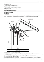
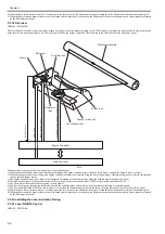
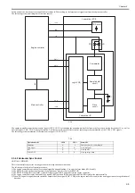
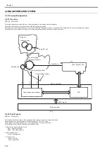
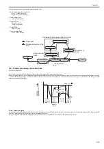
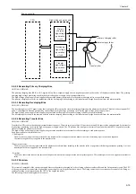
The following is the details of control procedure.
1) The engine controller controls the laser control signal during unblanking (*) to emit the laser diode (LD) forcibly.
2) The BD PCB exists on the scanning route of the laser beam, which is sent to the BD PCB.
3) The BD PCB detects this laser beam, creates BD input signal (/BDI) and sends it to the engine controller.
4) The engine controller creates horizontal sync signals (/BD) based on /BDI signal and sends the /BD signal to the main controller.
5) When /BD signal is input, the main controller outputs the video signal (VD0, /VD0) to the engine controller to adjust the writing position in image horizontal
direction.
*: Unblanking period
The period during which the laser diode is emitted in non-image area.
2.3.3 Laser Control
2.3.3.1 Auto Power Control (APC)
0019-3465
LBP3100 / LBP3010B
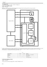
This is the control to emit a constant level of laser diode.
There are two types of APC; initial APC (note 1), and line space APC (note 2). The laser driver executes the same procedure for both controls. The following is the
details of the control procedure.
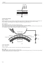
1) When the laser control signal enters APC mode (CNT0=H, CNT1=L), the laser driver emits LD in APC mode.
2) The emission level of LD is detected with photo diode (PD), converted from current output to voltage, and compared with the standard voltage (voltage equivalent
to the target laser level).
3) The laser driver controls the laser current to achieve the voltage of LD target level.
4) When the laser control signal enters LD forced OFF mode, the LD is forcibly turned off. The laser driver saves the adjusted laser intensity to the capacitor (C1).
2.3.3.2 Auto Power Control (APC)
0025-1143
LBP6000 / LBP6000B
This is the control to emit a constant level of laser diode.
There are two types of APC; initial APC (note 1), and line space APC (note 2). The laser driver executes the same procedure for both controls. The following is the
details of the control procedure.
1) When the laser control signal enters APC mode (CNT0=H, CNT1=L), the laser driver emits LD in APC mode.
2) The emission level of LD is detected with photo diode (PD), converted from current output to voltage, and compared with the standard voltage (voltage equivalent
to the target laser level).
3) The laser driver controls the laser current to achieve the voltage of LD target level.
4) When the laser control signal enters LD forced OFF mode, the LD is forcibly turned off. The laser driver saves the adjusted laser intensity to the capacitor (C1).
2.3.4 Laser Scanner Motor Control
2.3.4.1 Overview
0019-5265
LBP3100 / LBP3010B
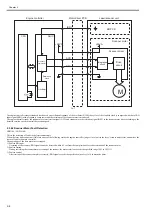
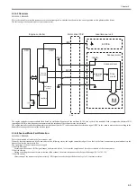
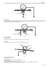
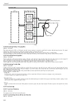
This is the control to rotate the scanner motor at a constant speed to emit the laser beam on the correct position on the photosensitive drum.
The following is the control circuit of the scanner motor.
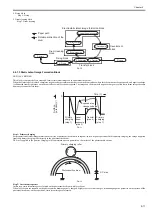
1. Initial APC
APC that is executed during initial rotation. APC adjusts laser intensity.
2. Line space APC
APC that is executed during printing. Laser intensity for one line is adjusted before writing one line.
1. Initial APC
APC that is executed during initial rotation. APC adjusts laser intensity.
2. Line space APC
APC that is executed during printing. Laser intensity for one line is adjusted before writing one line.
Содержание LBP6000 Series
Страница 1: ...Sep 8 2010 Service Manual LBP6000 6018 3010 3100 3150 Series...
Страница 2: ......
Страница 6: ......
Страница 12: ...Contents...
Страница 13: ...Chapter 1 PRODUCT DESCRIPTION...
Страница 14: ......
Страница 16: ......
Страница 28: ......
Страница 29: ...Chapter 2 TECHNICAL REFERENCE...
Страница 30: ......
Страница 74: ......
Страница 75: ...Chapter 3 DISASSEMBLY AND ASSEMBLY...
Страница 76: ......
Страница 119: ...Chapter 4 MAINTENANCE AND INSPECTION...
Страница 120: ......
Страница 122: ......
Страница 126: ......
Страница 127: ...Chapter 5 TROUBLESHOOTING...
Страница 128: ......
Страница 130: ......
Страница 137: ...Chapter 6 APPENDIX...
Страница 138: ......
Страница 140: ......
Страница 144: ......
Страница 145: ...Sep 8 2010...
Страница 146: ......

