Chapter 2
2-33
2.7.2.2 General description
0025-1186
LBP6000 / LBP6000B
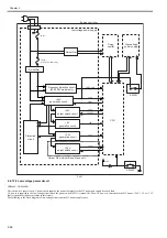
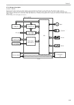
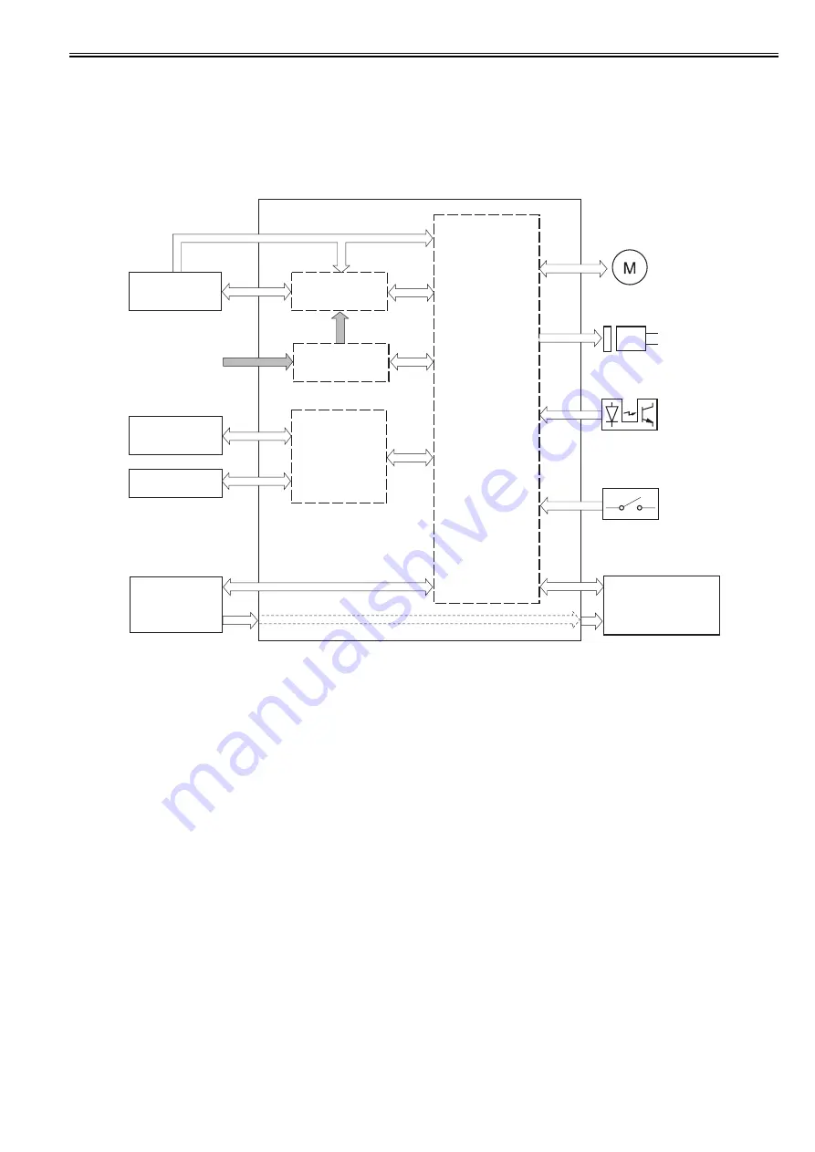
Engine controller is the circuit to control the operation sequence of the host machine and it is controlled by the CPU inside the engine controller.
When the power is turned ON and DC power is supplied through the low voltage power inside engine controller, CPU starts the printer operation control.
Then, CPU drives the loads such as laser diode, motors and solenoids etc. according to the image data that is input by the main controller when status becomes
stand-by mode.
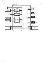
The following is the block diagram of this circuit.
F-2-42
AC input
Fixing unit
Motor
Transfer roller
High-voltage
power supply
Low-voltage
power supply
Laser/scanner
unit
Solenoid
Main controller
Toner Cartridge
Sensor
CPU
Switch
Engine controller
Fixing control
Содержание LBP6000 Series
Страница 1: ...Sep 8 2010 Service Manual LBP6000 6018 3010 3100 3150 Series...
Страница 2: ......
Страница 6: ......
Страница 12: ...Contents...
Страница 13: ...Chapter 1 PRODUCT DESCRIPTION...
Страница 14: ......
Страница 16: ......
Страница 28: ......
Страница 29: ...Chapter 2 TECHNICAL REFERENCE...
Страница 30: ......
Страница 74: ......
Страница 75: ...Chapter 3 DISASSEMBLY AND ASSEMBLY...
Страница 76: ......
Страница 119: ...Chapter 4 MAINTENANCE AND INSPECTION...
Страница 120: ......
Страница 122: ......
Страница 126: ......
Страница 127: ...Chapter 5 TROUBLESHOOTING...
Страница 128: ......
Страница 130: ......
Страница 137: ...Chapter 6 APPENDIX...
Страница 138: ......
Страница 140: ......
Страница 144: ......
Страница 145: ...Sep 8 2010...
Страница 146: ......

