background image


CANNON Instrument Company® | In-Depth Operation 

43 


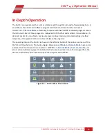
CAV 4.1 GUI 

The CAV 4.1 GUI is the software program shown on the touchscreen, embedded in the display hood of 
the CAV 4.1. The previous Getting Started


section of this manual introduces the operator to the basic 

usage of the CAV 4.1 GUI. This section, including Table 13, provides more in-depth instructions.  

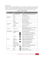
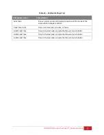
Table 13 — GUI Screen Details 

Area 

Button 

Action 

Main screen 

menu 

Local/Remote Mode 

Toggles between the two control modes 

Users 

Opens login menu 

Results 

Opens local results log 

Errors 

Opens local errors log 

Help 

Opens help menu 

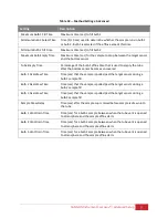
Bath screen 

menu 

Settings 

Opens settings menu 

Tube Calibration 

Opens tube calibration menu 

Methods 

Opens methods menu 

Services 

Opens services 

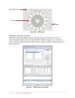
Carousel 

Positions 1 – 14 

Each position displays the title of the sample. 

Click to configure a sample. 

Click center of carousel for bath options. 

Screen sliders 

Left/right arrows 

Slides between screens 

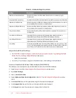
Status 

Sensors 

Displays the status of the bath sensors: 

Red – unavailable; Green – covered; Gray – 

uncovered. Click to train sensors. 

TE Cooler 

Displays the status of the TE cooler. 

Click to turn on/off the TE cooler. 

Current 

temperature 

Displays the current bath temperature. 

Click to calibrate temperature. 

Target 

temperature 

Displays the target temperature. 

Click to set target temperature. 

Activity message 

Displays current activity 

Preheater temperature 

Displays current preheater temperature 

Actions 

Run/Stop 

Click to start or stop a run 

Wash 

Click to run a wash 

Pause 

Click to pause a run or wash 

Содержание CAV 4.1

Страница 1: ...Operation Manual Single Bath Automated Kinematic Viscometer CAV 4 1...

Страница 2: ...ny CAV and VISCPRO are registered trademarks of Cannon Instrument Company Contact Address CANNON Instrument Company 2139 High Tech Road State College PA 16803 USA Phone 1 814 353 8000 1 800 676 6232 F...

Страница 3: ...Set Vacuum and Pressure Components 19 Set Vacuum and Pressure Touchscreen 23 Adjust the Default Wash Settings Touchscreen 24 Run a Wash Touchscreen 25 Train the Sensors Touchscreen 26 Run a Sample Tes...

Страница 4: ...52 Advanced Setup 53 Calibrate Viscometer Tube VISCPRO II 53 Method Test Settings 54 Print Method Settings 54 Edit Method Settings 54 Adjust Default Wash Settings 58 Create a Standard CAV Data Table A...

Страница 5: ...4 1 Screen 16 Figure 17 Temperature Settings Screen 16 Figure 18 Target Temperature Entry Screen 17 Figure 19 Thermometer Access Hole 18 Figure 20 Temperature Calibration Screen 18 Figure 21 Green Ch...

Страница 6: ...n 44 Figure 56 VISCPRO Interface Window 44 List of Tables Table 1 Specifications and Compliances 2 Table 2 Packing List Main Components 4 Table 3 Packing List installation 5 Table 4 Packing List Tools...

Страница 7: ...ures to enhance lab productivity reduce costs and improve data quality CANNON CAV 4 1 Single Bath Benchtop Kinematic Viscometer comes with two 14 position sample carousels two viscometer tubes one set...

Страница 8: ...required 8 mL sample 15 mL solvent per test as little as 3mL with fast run tubes Viscosity range 0 5 mm s to 10 000 mm2 s in 100 fold increments depending on viscometer tubes selected Fast run tubes a...

Страница 9: ...and or void the manufacturer s warranty Handle and transport the unit with care Sudden jolts or impacts may cause damage to components Observe all warning labels Never remove warning labels Never ope...

Страница 10: ...on as they are received Caution Many components are fragile Use caution when moving and handling the CAV 4 1 and accessories 1 Carefully unpack the entire contents of the shipment 2 Refer to the packa...

Страница 11: ...ottle caps for GL 38 bottles 4 65 3201 20 micron filters 4 65 0047 Waste 1 2 white nylon tubing 15 ft 62 1500 3 1 2 white nylon elbows 2 62 1500 2 1 2 white nylon tees 2 62 1500 4 Table 4 Packing List...

Страница 12: ...iption Hose connections Complete CAV 4 1 1 8 blue FEP tubing 25 ft MAINS AC power cable 1 2 white nylon tubing 15 ft Waste receiver Bottle caps for GL 38 bottles 4 Solvent 20 micron filters 4 Silicone...

Страница 13: ...top of the waste receiver must be lower than the waste outlets on the back of the instrument 3 Place the solvent bottles alongside or beneath the CAV 4 1 4 Measure and cut the 1 8 blue FEP tubing to u...

Страница 14: ...to enable combining both waste tubes into one tube before entering the waste receiver A brass elbow is also provided to connect the waste tubing to the waste receiver 8 Measure and cut the 1 2 white n...

Страница 15: ...scosity of the fluid depends upon the temperature of the bath during most operations Refer to Table 6 for proper bath fluid selection Table 6 Silicone Bath Fluid Selection Bath operating range Recomme...

Страница 16: ...e CAV 4 1 instrument and let the bath cool to room temperature 2 Lift the hood to access the top of the bath 3 Remove the float from the top of the bath and set aside This provides the opening to fill...

Страница 17: ...cable fill line on the bath The top line is for lower temperatures 100 C and the bottom line is for higher temperatures 135 C and above Refer to Figure 7 and Figure 8 Figure 7 Filling Bath with 10 cSt...

Страница 18: ...aution to avoid exposure to hot bath fluid 1 Turn off power to the CAV 4 1 instrument and allow bath to cool to room temperature Warning When working with the bath in any capacity and especially when...

Страница 19: ...g onto bath drain leaving at least above the hose on the nozzle The hose must cover the large end of the nozzle without making contact with the bath itself There must be adequate room above the hose t...

Страница 20: ...priate bath drainage container Refer to Figure 12 Figure 12 Hose Draining into Fluid Container 6 Use the Open End wrench to gently open the drain by turning the exposed portion counter clockwise Figur...

Страница 21: ...tom of the bath Figure 15 Fully Closed Bath Drain Plug 9 Now that bath is empty return the hood and panel to their original positions reversing previous steps to remove them Procedure is complete Conn...

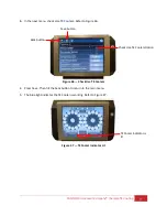
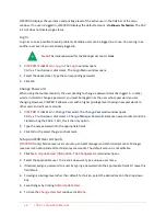
Страница 22: ...nterface or GUI located on the instrument s touchscreen 1 From the main screen click the target temperature button for the bath This opens the temperature settings screen Figure 16 Main CAV 4 1 Screen...

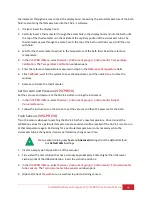
Страница 23: ...The temperature calibration must be verified any time the instrument is moved the bath fluid is refilled or a new operating temperature is used The instrument is calibrated by inserting the thermomet...

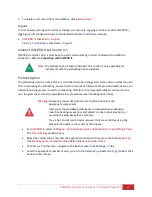
Страница 24: ...ame hole in the top of the bath that is used to fill the unit with fluid Refer to Figure 19 Figure 19 Thermometer Access Hole 3 Wait for the thermometer to adjust to the temperature of the bath fluid...

Страница 25: ...ave the adjustment and then click Back to return to the main screen 8 Remove and clean the thermometer and then store safely Set Vacuum and Pressure Components Set the vacuum and pressure of the CAV 4...

Страница 26: ...n either side of the top of the bath and rotate to lock into the up position Figure 23 Access Pin on One Side 3 Gripping the access pins push against the outer chassis to pull out the inner chassis Fi...

Страница 27: ...e bath control wing swings out Figure 25 Side of Chassis with Latch with Close up of Latch 5 As the bath control wing swings out it allows access to the Vacuum and Pressure knobs Adjust as necessary F...

Страница 28: ...uum Pressure Gauge Figure 28 Front View of Bath Control Wing with Vacuum and Pressure Knobs 6 Repeat the steps in reverse order to slide the chassis back into place and commence operation Vacuum Contr...

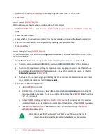
Страница 29: ...the instrument is put back together use the GUI Touchscreen to adjust the vacuum and pressure settings 1 From the main screen select Bath to open the bath screen options Figure 29 Bath Screen 2 From t...

Страница 30: ...Verify and adjust the default wash settings prior to running a wash for the first time Note The CAV 4 1 wash settings are defined in the method settings of the last run test When starting the CAV 4 1...

Страница 31: ...when installing the CAV 4 1 is to run a wash The CAV 4 1 is a uniquely useful instrument in that it is capable of automatically washing the sample tube saving valuable operator time Hence prior to tr...

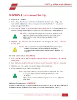
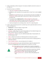
Страница 32: ...vial into position 2 3 From the main menu click the Tube button This opens the Train Screen window Note Uncheck the Prewash or Trip Points Only box options 4 Press the Start Training button Refer to F...

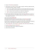
Страница 33: ...e Figure 37 Sample ID Entry Field 5 Enter the viscosity value in cSt of the test oil Then click the green checkmark to submit the entry and return to the Main Menu screen 6 Click the Run button 7 When...

Страница 34: ...ual 3 Click the Export button A field entry screen opens 4 Enter the sample file name Then click the green checkmark to submit it A Save As window opens 5 Select the desired location to save the data...

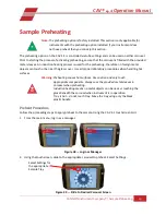
Страница 35: ...touch or be near the glass cover Use all proper laboratory procedures when handling hot surfaces Warning Preheating causes hot surfaces Use caution and only touch appropriate components Always use th...

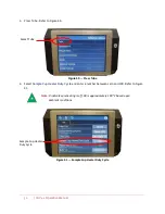
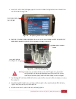
Страница 36: ...s Tube 4 Select Sample Cup Heater Duty Cycle and enter a number between zero and 100 Refer to Figure 41 Note 0 indicates preheating is off 90 is approximately 100 C based upon ambient conditions Figur...

Страница 37: ...ng Sample carousel and metal sleeves are hot The glass may also be hot due to proximity of the sample carousel and vials Do not touch Do not allow any metal items other than the metal sleeves to touch...

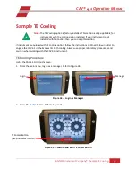
Страница 38: ...nt is equipped with TE cooling option follow the instructions outlined below in order to engage the CAV 4 1 in thermoelectric bath cooling Always use proper laboratory procedures and caution when work...

Страница 39: ...to Figure 46 Figure 46 Check Use TE Coolers 4 Press Save Then hit the back button to return to the main menu 5 The blue light indicates the TE Cooler is working Refer to Figure 47 Figure 47 TE Cooler...

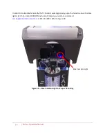
Страница 40: ...ler is working properly open the hood to ensure the blue light is lit If not contact CANNON Instrument Company service for assistance at service cannoninstrument com or 814 353 8000 Refer to Figure 48...

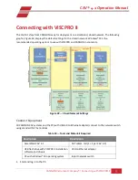
Страница 41: ...stem to use with VISCPRO and CANNON instruments Figure 49 Closed Network Settings Connect Equipment All CANNON CAV systems and the PC with USB 2 0 to Ethernet adapter connect to the network switch usi...

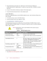
Страница 42: ...VISCPRO software The only way to change these values is by directly editing the registry Refer to Table 11 Caution Editing registry entries may be hazardous to the operation of your Windows system Ta...

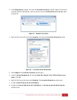
Страница 43: ...n and select Properties This opens the Connection Properties window Figure 51 Connection Properties Window 4 Click Configure The Controller Properties window opens 5 Select the Power Management tab Un...

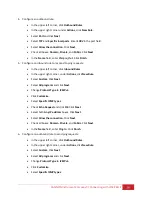
Страница 44: ...ion Click OK Configure Firewall Rules The Windows Firewall on the PC on which VISCPRO is installed must be configured to permit inbound outbound and ping communications on default port 1982 1 If open...

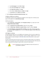
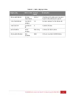
Страница 45: ...ound Rules In the upper right corner under Actions click New Rule Select Custom Click Next Select All programs and click Next Change Protocol Type to ICMPv4 Click Customize Select Specific ICMP types...

Страница 46: ...ing change the setting to Disabled Under Device Manager Universal Serial Bus controllers double click on the appropriate USB hub select the Power Management tab and uncheck Allow the computer to turn...

Страница 47: ...Remote Client Name 10 0 1 2 IP address of the Ethernet connection to which the instrument connects InstrumentAddress Instrument Address 1 4 Numeric address for the instrument Instrument ID Instrument...

Страница 48: ...wn data set A data set consists of a run of tests test results and error logs Common instrument settings method templates and equipment status are shared between the programs The operating status of t...

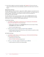
Страница 49: ...calibration menu Methods Opens methods menu Services Opens services Carousel Positions 1 14 Each position displays the title of the sample Click to configure a sample Click center of carousel for bath...

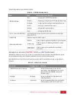
Страница 50: ...rising the general interface application and instrument analysis specific modules A typical VISCPRO II interface displays an open instrument window analysis log application specific status window and...

Страница 51: ...Matching Click to open the VI Matching information status window instrument Click to open a status window for a particular instrument Manage User Accounts VISCPRO II CAV 4 1 GUI Touchscreen VISCPRO II...

Страница 52: ...allows a user with a higher privilege level to assign new passwords to other users and edit user accounts 1 VISCPRO II click Main Change Password The Change Password window opens CAV 4 1 Touchscreen c...

Страница 53: ...with the provided metal sleeves An induction heating process is used for preheating therefore no foreign metal objects can touch or be near the glass cover Use all proper laboratory procedures when h...

Страница 54: ...rument Window opens Caution When multiple instruments CAV 2100 2200 CAV 4 2 CAV 4 1 are connected to the same VISCPRO II application verify that all instruments have completed their current operations...

Страница 55: ...Set Vacuum and Pressure VISCPRO II Set the vacuum and pressure of the CAV 4 1 before running the instrument 1 In the VISCPRO II Menu select Service instrument group instrument Adjust Vacuum Pressure 2...

Страница 56: ...current temperature and target temperature icons are green indicating that the bath has been temperature calibrated at that temperature If any other condition is indicated refer to Calibrate Temperatu...

Страница 57: ...left click to select a contiguous range of entries Ctrl left click to select multiple entries Configure enables editing of all values for the selected entry These localized changes do not affect the d...

Страница 58: ...in the Sample Action field Once the entire test run finishes the tray pauses No additional samples may be added to the run Click Resume to clear all data for the active tray View Test Results VISCPRO...

Страница 59: ...of the viscometer tube run in only the lower bulb 2 Follow the procedures in Run a Sample Test VISCPRO II to prepare load and run all of the calibration standards with setting Verify Known KV 3 When...

Страница 60: ...et for that test Verify Known KV must be used when running a calibration sample test Print Method Settings For VISCPRO II select Configure instrument group instrument Print Instrument Settings The Sel...

Страница 61: ...ple drop to coat the inside of the tube with the sample material Soak Time Units Time unit in seconds minutes or hours Bulb1 Soak Time Time to thermal soak a sample that draws only into bulb 1 Bulb2 S...

Страница 62: ...Fill Time Max time sec to fill the solvent bulb with solvent A Maximum Solvent B Fill Time Max time sec to fill the solvent bulb with solvent B Maximum Solvent C Fill Time Max time sec to fill the so...

Страница 63: ...1 Overdraw Time Time sec that the sample is pulled past the target sensor during a bulb 1 sample fill Bulb 2 Overdraw Time Time sec that the sample is pulled past the target sensor during a bulb 2 sa...

Страница 64: ...ux difference between the two Use Either If Use Percent Difference and Use Efflux Difference are both set then if true a match between two determinations is made if either criteria is met if false bot...

Страница 65: ...mple KE contribution of the kinetic energy correction to the measured viscosity Known KV Value entered for the known KV of the sample Diff KV difference between the measured KV and the known KV Temp A...

Страница 66: ...0 CAV 4 1 Operation Manual 8 Click OK The software prompts user to save the analysis If selecting YES the analysis is displayed after it is saved If selecting NO the analysis displays but is not saved...

Страница 67: ...er interface To update the CAV 4 1 GUI software log out of the user interface and run the UI updater instead Firmware updates this code controls the bath sample handlers and valve controls It is insta...

Страница 68: ...ter the CAV finishes its rebooting routine power cycle the unit by completely turning it off using the power switch on the hood Wait 10 seconds and then turn it back on Update the Controller Firmware...

Страница 69: ...ature 2 Drain the silicone bath fluid into a clean container Save the fluid to refill the bath 3 Raise the hood 4 Note the solvent line connections for future reconnection Gently unscrew the solvent l...

Страница 70: ...a tube is changed 17 Train the sensors 18 Verify the Default Wash and Method Settings especially Verify Known KV for the bath 19 Calibrate the new viscometer tube Replace Power Supply The CAV 4 1 pow...

Страница 71: ...l not be binding upon the Company unless placed in writing and approved by an officer of the Company Reagent and Chemical Warranty Cannon Instrument Company the Company warrants all reagents and chemi...

Страница 72: ...location A detailed explanation of the reason for the return If the product is not covered by warranty the customer will be provided with an estimate of the repair costs and asked for approval before...

Страница 73: ...2139 High Tech Road State College PA 16803 USA 800 676 6232 814 343 8000 Fax 814 353 8007 sales cannoninstrument com www cannoninstrument com CANNON INSTRUMENT COMPANY rev MAY4 2022...

Отзывы: