


CANNON Instrument Company® | Getting Started
7
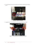
Connect Hoses
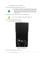
Assemble the CAV 4.1 on a secure surface with sufficient room behind the instrument to maintain a
clear airflow and allow for unimpeded connection of the solvent inlet and waste outlet tubing.
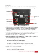
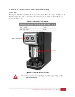
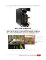
Figure 2 — Tubing Connections (Rear Close Up)
1.
Place the CAV 4.1 on a solid, level workbench located near a MAINS AC power connection capable of
providing sufficient current (10 A at 115 V
AC
) to the CAV 4.1. Depending on the materials tested,
solvent used, and laboratory regulations, the work area may also need to be equipped with a
ventilation system.
2.
Place the waste receiver beneath the CAV 4.1. In order to promote proper gravity drainage, the top
of the waste receiver must be lower than the waste outlets on the back of the instrument.
3.
Place the solvent bottles alongside or beneath the CAV 4.1.
4.
Measure and cut the
1
∕
8
" blue FEP tubing to use as the solvent tubing. Each piece of tubing must run
from the solvent inlet well to the bottom of a solvent bottle.
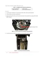
5.
Connect the solvent tubing to the CAV 4.1:
a.
Remove the cover plate from the solvent inlet well.
b.
Thread the tubing through the solvent inlets on the back of the lid.
c.
Unscrew the appropriate compression connector and slide it onto the tubing.
d.
Slide the tubing onto the flared inlet pipe and hand tighten the compression connector.
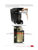
6.
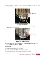
Insert the solvent tubing into the solvent bottle:
a.
Thread the tubing through the bottle cap.
b.
Screw a 20 micron filter onto the end of the tubing.
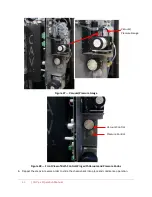
MAINS Power
Waste Line
Solvent
Vacuum Exhaust
Solvent
Waste Line
Communication
Ports
Fuses


