Document type:
Title:
Revision date:
Revision:
User's Manual (MUT)
Mod. V1724 8 Channel 14bit - 100MS/s Digitizer
06/11/2007
7
NPO:
Filename:
Number of pages:
Page:
00103/05:V1724x.MUTx/07 V1724_REV7.DOC
63
61
5. Installation
−
The Mod. V1724 fits into all 6U VME crates.
−
VX1724 versions require VME64X compliant crates
−
Turn the crate OFF before board insertion/removal
−
Remove all cables connected to the front panel before board insertion/removal
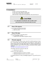
CAUTION
ALL CABLES MUST BE REMOVED FROM THE FRONT PANEL
BEFORE EXTRACTING THE BOARD FROM THE CRATE!
5.1.
Power ON sequence
To power ON the board follow this procedure:
1. insert the V1724 board into the crate
2. power up the crate
5.2.
Power ON status
At power ON the module is in the following status:
•
the Output Buffer is cleared;
•
registers are set to their default configuration (see § 4)
5.3. Firmware
upgrade
The board can store two firmware versions, called STD and BKP respectively; at Power
On, a microcontroller reads the Flash Memory and programs the module with the
firmware version selected via the JP2 jumper (see § 2.6), which can be placed either on
the STD position (left), or in the BKP position (right). It is possible to upgrade the board
firmware via VME, by writing the Flash; for this purpose, download the software package
available at:
http://www.caen.it/nuclear/product.php?mod=V1724
The package includes the new firmware release file:
•
v1724_rN_revX.Y_W.Z..rbf
and the V1724 firmware upgrade tool:
•
CAENDigitizerUpgrade.exe (windows executable)
•
CAENDigitizerUpgrade tool (source code and VC++ project)
For upgrading the firmware, utilizing CAENDigitizerUpgrade.exe, open a DOS shell, then
launch


