


Document type:
Title:
Revision date:
Revision:
User's Manual (MUT)
Mod. V1724 8 Channel 14bit - 100MS/s Digitizer
06/11/2007
7
NPO:
Filename:
Number of pages:
Page:
00103/05:V1724x.MUTx/07 V1724_REV7.DOC
63
24
N
LOC
= 0 means “default size events”, i.e. the number of memory locations is the
maximum allowed.
N
LOC
= N1, with the constraint 0<N1<½NS, means that one event will be made of 2
⋅
N1
samples.
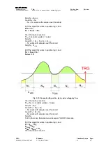
3.3.5. Event
structure
An event is structured as follows:
−
identifier (Trigger Time Tag, Event Counter)
−
samples caught in the acquisition windows
The event is stored in the board memories and can be readout via VME; data format is
32 bit long word, therefore each long_word contains 2 samples.
The event format is the following:
31 30 29 28 27 26 25 24 23 22 21 20 19 18 17 16 15 14 13 12 11 10 9 8 7 6 5 4 3 2 1 0
EVENT SIZE
CHANNEL MASK
TRIGGER TIME TAG
1
0
1
0
reserved
EVENT COUNTER
reserved
SAMPLE [1] – CH[0]
SAMPLE [0] – CH[0]
SAMPLE [3] – CH[0]
SAMPLE [2] – CH[0]
SAMPLE [N-1] – CH[0]
SAMPLE [N-2] – CH [0]
SAMPLE [1] – CH[1]
SAMPLE [0] – CH[1]
SAMPLE [3] – CH[1]
SAMPLE [2] – CH[1]
SAMPLE [N-1] – CH[1]
SAMPLE [N-2] – CH [1]
HEA
D
ER
DA
T
A
C
H
0
D
A
T
A
CH1
SAMPLE [1] – CH[7]
SAMPLE [0] – CH[7]
SAMPLE [3] – CH[7]
SAMPLE [2] – CH[7]
SAMPLE [N-1] – CH[7]
SAMPLE [N-2] – CH [7]
DA
T
A
CH
7
BOARD-ID
0 0
0 0
0 0
0 0
0 0
0 0
0 0
0 0
0 0
0 0
0 0
0 0
0 0
0 0
0 0
0 0
0 0
0 0
PATTERN
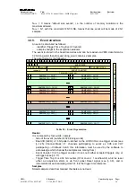
Table 3.2 : Event Organization
Header
It is composed by four words, namely:
−
Size of the event (number of 32 bit long words)
−
Board ID (GEO); a 16 bit pattern, latched on the LVDS I/O as one trigger arrives (see
§ 4.25); Channel Mask (=1: channels participating to event; ex CH5 and CH7
participating
→
Ch Mask: 0xA0, this information must be used by the software to
acknowledge which channel the samples are coming from)
−
Event Counter: It is the trigger counter; it can count either accepted triggers only, or
all triggers (see § 4.17).
−
Trigger Time Tag: It is a 32 bit counter (31 bit count + 1 overflow bit), which is reset
either as acquisition starts or via front panel Reset signal (see § 3.8), and is
incremented at each sampling clock hit. It is the trigger time reference.
Samples
Stored samples; data from masked channels are not read.