


Document type:
Title:
Revision date:
Revision:
User's Manual (MUT)
Mod. V1724 8 Channel 14bit - 100MS/s Digitizer
06/11/2007
7
NPO:
Filename:
Number of pages:
Page:
00103/05:V1724x.MUTx/07 V1724_REV7.DOC
63
21
Subsequentially acquisition is stopped either:
−
resetting the RUN/STOP bit (bit[2]) in the Acquisition Control register (bits [1:0] of
Acquisition Control must be set to REGISTER-CONTROLLED RUN MODE
or S-IN
CONTROLLED RUN MODE)
−
driving S_IN signal low (bits [1:0] of Acquisition Control set to 01)
3.3.2.
Gate and Sample mode acquisition
It is possible to use the S_IN signal (see § 2.4.2) as “gate” to enable samples storage.
The samples produced by the 100 MHz ADC are stored in memory only if they are
validated by the S_IN signal, otherwise they are rejected; data storage takes place by
couples of samples (two 32 bit long words) per time. Two operating modes are foreseen,
as decrbed in the following.
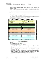
3.3.2.1. Gate
mode
In Gate mode all the values sampled as the S-IN signal is active (high) are stored; for this
purpose it is necessary to:
Set bits [1:0] of Acquisition Control register to S-IN GATE MODE
Set bit [0] of Channel Configuration Register (see § 4.12) to 0
All the values sampled as the S-IN signal is active (high) are stored.
D0
D1
D2
D3
D4
D5
D6
D7
D8
D9
D10
SAMPLING CLOCK
S-IN
ADC DATA
S0
S4
S8
S12
S16
S 20
S 24
S28
S32
S 36
S40
D11
D12
S44
S48
S52
D9
D10
D11
D12
D2
D2
D3
D2
D3
D4
D2
D3
D4
D5
D2
D3
D4
D5
D6
D2
D3
D4
D5
D6
D2
D3
D4
D5
D6
D2
D3
D4
D5
D6
D9
D2
D3
D4
D5
D6
D9
D2
D3
D4
D5
D6
D9
MEMORY
BUFFER
D2
D3
D4
D5
D6
D9
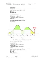
Fig. 3.5: Data Storage
1
in Gate mode
1
Underscored = stored


