Document type:
Title:
Revision date:
Revision:
User's Manual (MUT)
Mod. V1724 8 Channel 14bit - 100MS/s Digitizer
06/11/2007
7
NPO:
Filename:
Number of pages:
Page:
00103/05:V1724x.MUTx/07 V1724_REV7.DOC
63
56
Bit
Function
[0]
0 = TRG/CLK are NIM I/O Levels
1 = TRG/CLK are TTL I/O Levels
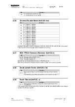
4.26.
Channel Enable Mask (0x8120; r/w)
Bit
Function
[7]
0 = Channel 7 disabled
1 = Channel 7 enabled
[6]
0 = Channel 6 disabled
1 = Channel 6 enabled
[5]
0 = Channel 5 disabled
1 = Channel 5 enabled
[4]
0 = Channel 4 disabled
1 = Channel 4 enabled
[3]
0 = Channel 3 disabled
1 = Channel 3 enabled
[2]
0 = Channel 2 disabled
1 = Channel 2 enabled
[1]
0 = Channel 1 disabled
1 = Channel 1 enabled
[0]
0 = Channel 0 disabled
1 = Channel 0 enabled
Enabled channels provide the samples which are stored into the events (and not erased).
The mask cannot be changed while acquisition is running.
4.27.
ROC FPGA Firmware Revision (0x8124; r)
Bit
Function
[31:16] Revision date in Y/M/DD format
[15:8] Firmware Revision (X)
[7:0]
Firmware Revision (Y)
Bits [31:16] contain the Revision date in Y/M/DD format.
Bits [15:0] contain the firmware revision number coded on 16 bit (X.Y format).
4.28.
Downsample Factor (0x8128; r/w)
Bit
Function
[31:0]
This register allows to set
N
: sampling frequency will be divided by
N+1.
Downsampling is enabled via Acquisition Control register; see § 4.17
4.29.
Event Stored (0x812C; r)
Bit
Function
[31:0]
This register contains the number of events currently stored in the
Output Buffer
This register value cannot exceed the maximum number of available buffers according to
setting of buffer size register.


