74
28.6. COMBUSTION ADJUSTMENT AND VERIFICATION
To enjoy the efficiency of our oil burning units, you
must respect the following criterion:
Oil burning units must be connected to flue pipes
having at all times a sufficient draft to ensure an
efficient and safe operation of unit.
Before turning on the oil unit, make sure that the
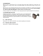
sealed vision cap (SE53352) is installed and
secured on the vision tube with the screw provided.
The chamber is calibrated so that there is a slight
positive pressure, which optimizes the efficiency of
combustion. The presence of the sealed vision cap
thus prevents the return of oil odor.
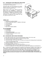
CHECK LIST
:
•
Selection of nozzle and head
•
Nozzle / electrodes position in relation to the head
•
Pump pressure
•
Oil line is bleed.
•
Fan speed
•
Barometric damper position
TOOLS REQUIRED:
•
Draft gauge
•
Smoke tester
•
Pump pressure gauge
•
Nozzle and electrodes position tester
•
Combustion tester
28.6.1. COMBUSTION VERIFICATION PROCEDURE:
A- Drill a 9/32" diameter hole in the evacuation pipe approximately 18" from the outlet.
B- Close the door and the air intake(s) of the wood burning furnace.
C- Light the burner for at least 10 to 15 minutes.
D- Over the fire draft = 0.01 to 0.02 in.w.c. (the draft over the fire must be measured by the scealed cap
of the vision tube’s pulsation trap).
E- Smoke test between 0 and 1 on the shell bacharach scale (traces).
F- Draft in the chimney = 0.02 in.w.c.
G- Percentage of excess air = 12%, 13.5% co
2
, 2.3% o
2
.
H- Average efficiency of 85% based on the type of burner and its input.
I- Burner’s air adjustement: 0-4. Tighten all the locking screws after completing the final adjustment.
N.B. The barometric damper provided with the appliance must be properly installed on the flue pipe of the
oil burning unit. The purpose of the damper is to adjust the draft in the evacuation pipe of the oil burning
unit to the recommended level. Since the evacuation pipe of the oil burning unit is connected on the
evacuation pipe of the wood burning furnace, the minimum draft to be respected is 0.04 IN.W.C. in the
evacuation pipe of the wood burning side, at all times.
In fact, a barometric damper that would be
opened too wide could cause an important loss of draft in the evacuation pipe of the wood burning
furnace.
Содержание PF01015
Страница 10: ...10 ADD ON WOOD ONLY WOOD ELECTRIC WOOD OIL ...
Страница 13: ...13 INSTALLATION AND OPERATION INSTRUCTIONS CADDY ADD ON SERIAL INSTALLATION PF01015 ...
Страница 16: ...16 Option 3 Option 4 ...
Страница 17: ...17 EXAMPLE 1 EXAMPLE 2 ...
Страница 23: ...23 REQUIRES 2 RELAY SPNO SPNC WHITE ROGERS P N 90 380 NOT INCLUDED AND 24V AVAILABLE ON EXISTING FURNACE ...
Страница 24: ...24 13 ELECTRICAL DIAGRAM FOR SERIAL FURNACE VIA MOTOR REQUIRES 1 RELAY 51035 WITH 1 JUNCTION BOX NOT INCLUDED ...
Страница 63: ...63 20 GENERAL ELECTRICAL DIAGRAM STANDALONE FURNACE ...
Страница 64: ...64 21 ELECTRICAL DIAGRAM FOR PARALLEL FURNACE ...
Страница 65: ...65 22 ELECTRICAL DIAGRAM FOR ELECTRIC UNIT ...
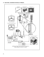
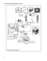
Страница 78: ...78 31 ELECTRICAL DIAGRAM BECKETT OIL UNIT ...
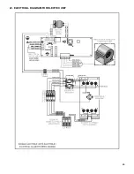
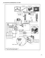
Страница 79: ...79 32 ELECTRICAL DIAGRAM RIELLO OIL UNIT ...
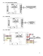
Страница 81: ...81 33 4 AIR CONDITIONNING DAMPER 33 5 HUMIDIFIER 33 6 HEAT PUMP ...
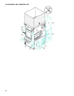
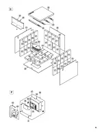
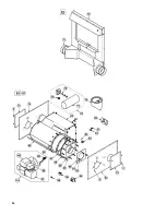
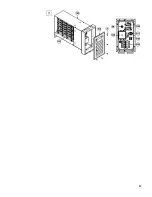
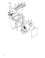
Страница 82: ...82 34 EXPLODED VIEW AND PART LIST ...
Страница 83: ...83 ...
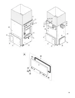
Страница 84: ...84 ...
Страница 85: ...85 ...
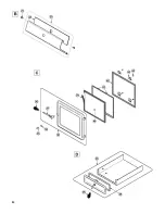
Страница 86: ...86 ...
Страница 87: ...87 ...
Страница 88: ...88 ...
Страница 89: ...89 ...

