34
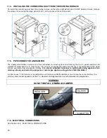
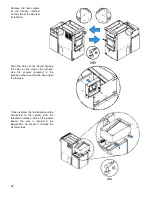
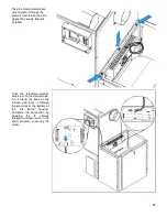
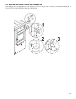
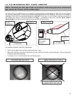
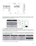
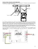
Once installed, install the chain linking the servomotor with the air inlet damper as shown above. The chain must have
a set of 1/8". When there is no call for heat, the air inlet damper must be completely closed and the chain must be
hooked to the servomotor at the “8 o’clock” position.
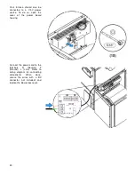
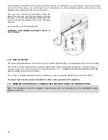
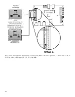
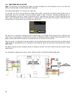
Then, you must connect the servomotor and the link
board. Take the wires out of the servomotor and enter
the wires in the wire cover through the grommet. Pull
them out through the grommet next to the link board
housing.
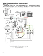
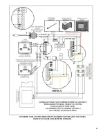
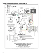
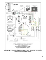
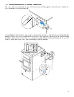
For connection, refer to wiring diagram.
WARNING: USE WIRING SUITABLE FOR 75 °C
(not included).
14.6. UNIT LOCATION
For a safe and quiet operation, the furnace must be leveled in both directions and supported evenly to ensure stability.
The furnace must be installed where outside air supply will be sufficient for proper combustion. In airtight houses, it
might be necessary to install an outside air inlet (See Section 14.11 - COMBUSTION AIR AND FRESH AIR INTAKE
ADAPTER INSTALLATION (OPTIONAL))
The furnace must be positioned so that the connector is as short as possible. Minimize the use of 90
o
elbows.
The owner must ensure a proper installation to allow a safe operation of the appliance
.
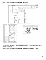
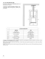
14.7. MINIMUM CLEARANCES TO COMBUSTIBLE MATERIALS AND FLOOR PROTECTION
N.B.: This appliance must be installed in accordance with the instructions on the certification plate
applied on the unit.
Содержание PF01015
Страница 10: ...10 ADD ON WOOD ONLY WOOD ELECTRIC WOOD OIL ...
Страница 13: ...13 INSTALLATION AND OPERATION INSTRUCTIONS CADDY ADD ON SERIAL INSTALLATION PF01015 ...
Страница 16: ...16 Option 3 Option 4 ...
Страница 17: ...17 EXAMPLE 1 EXAMPLE 2 ...
Страница 23: ...23 REQUIRES 2 RELAY SPNO SPNC WHITE ROGERS P N 90 380 NOT INCLUDED AND 24V AVAILABLE ON EXISTING FURNACE ...
Страница 24: ...24 13 ELECTRICAL DIAGRAM FOR SERIAL FURNACE VIA MOTOR REQUIRES 1 RELAY 51035 WITH 1 JUNCTION BOX NOT INCLUDED ...
Страница 63: ...63 20 GENERAL ELECTRICAL DIAGRAM STANDALONE FURNACE ...
Страница 64: ...64 21 ELECTRICAL DIAGRAM FOR PARALLEL FURNACE ...
Страница 65: ...65 22 ELECTRICAL DIAGRAM FOR ELECTRIC UNIT ...
Страница 78: ...78 31 ELECTRICAL DIAGRAM BECKETT OIL UNIT ...
Страница 79: ...79 32 ELECTRICAL DIAGRAM RIELLO OIL UNIT ...
Страница 81: ...81 33 4 AIR CONDITIONNING DAMPER 33 5 HUMIDIFIER 33 6 HEAT PUMP ...
Страница 82: ...82 34 EXPLODED VIEW AND PART LIST ...
Страница 83: ...83 ...
Страница 84: ...84 ...
Страница 85: ...85 ...
Страница 86: ...86 ...
Страница 87: ...87 ...
Страница 88: ...88 ...
Страница 89: ...89 ...

