48
15.2. HEATPUMP INSTALLATION
Note:
If a heat pump is connected to the Caddy, the electrical element must be installed to ensure an auxiliary heat
source. (PA01005-15kW, PA01055-18kW, PA01105-20kW)
Heat pump mode operates in "Furnace Only" mode only.
It is possible to connect a heat pump to the Caddy furnace. With a heat pump, the heating source priority menu is
inaccessible. Since the heat pump is the most efficient system to date, it becomes the priority heating source. An
external temperature sensor or a switch connected to the OT input becomes necessary to stop the operation of the
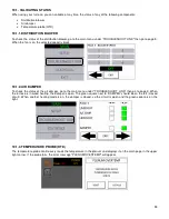
latter in very cold weather. When the heat pump is in defrost mode, the heat pump icon changes to indicate that the
electrical element is operating at the same time as the heat pump.
The same icon is used when a thermostat with 2 heating stages is connected and the electric unit is activated at the
same time as the heat pump. A thermostat with auxiliary or emergency mode is recommended to deactivate the heat
pump in cold weather without having to use a temperature sensor or switch on the furnace.
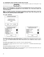
When the system is configured in heat pump mode, press the wood heating icon to switch the furnace to wood heating
mode. When the heating demand can no longer be answered by the wood, the furnace will automatically return to heat
pump mode.
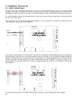
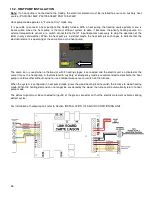
The defrost signal must be connected to input E of the green connector so that the electrical element activates during
defrost cycles.
For installation of heatpump coil, refer to Section INSTALLATION OF AN AIR CONDITIONING UNIT.
Содержание PF01015
Страница 10: ...10 ADD ON WOOD ONLY WOOD ELECTRIC WOOD OIL ...
Страница 13: ...13 INSTALLATION AND OPERATION INSTRUCTIONS CADDY ADD ON SERIAL INSTALLATION PF01015 ...
Страница 16: ...16 Option 3 Option 4 ...
Страница 17: ...17 EXAMPLE 1 EXAMPLE 2 ...
Страница 23: ...23 REQUIRES 2 RELAY SPNO SPNC WHITE ROGERS P N 90 380 NOT INCLUDED AND 24V AVAILABLE ON EXISTING FURNACE ...
Страница 24: ...24 13 ELECTRICAL DIAGRAM FOR SERIAL FURNACE VIA MOTOR REQUIRES 1 RELAY 51035 WITH 1 JUNCTION BOX NOT INCLUDED ...
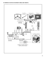
Страница 63: ...63 20 GENERAL ELECTRICAL DIAGRAM STANDALONE FURNACE ...
Страница 64: ...64 21 ELECTRICAL DIAGRAM FOR PARALLEL FURNACE ...
Страница 65: ...65 22 ELECTRICAL DIAGRAM FOR ELECTRIC UNIT ...
Страница 78: ...78 31 ELECTRICAL DIAGRAM BECKETT OIL UNIT ...
Страница 79: ...79 32 ELECTRICAL DIAGRAM RIELLO OIL UNIT ...
Страница 81: ...81 33 4 AIR CONDITIONNING DAMPER 33 5 HUMIDIFIER 33 6 HEAT PUMP ...
Страница 82: ...82 34 EXPLODED VIEW AND PART LIST ...
Страница 83: ...83 ...
Страница 84: ...84 ...
Страница 85: ...85 ...
Страница 86: ...86 ...
Страница 87: ...87 ...
Страница 88: ...88 ...
Страница 89: ...89 ...

