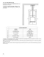
37
14.8. FLUE AND BAROMETRIC DRAFT CONTROL CONNECTION
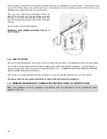
Before connecting the stove pipe, make sure you have removed any accessory from the flue
pipe such as the scraper, shovel, and the poker.
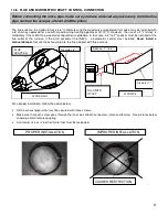
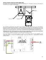
The flue outlet on the Caddy furnace is 6" in diameter and the wood only or wood/electric models may be installed with
a 6" chimney approved for use with wood burning heating appliances (2100°F). However, the use of a 7" chimney is
mandatory if the retrofit to a wood/oil configuration is probable. In that case, a 6" to 7" reducer must be installed at the
flue outlet of the furnace. If the draft exceeds 0.06 IN.W.C., a barometric control must installed.
Never install a
manual damper.
Secure the exhaust pipe to the flue adapter with three screws.
WOOD ONLY
Diameter 6"
WOOD/OIL
Reducer 7" to 6"
Diameter 7"
Unit oil
Max Caddy pipe
For a proper installation, follow the advice below:
•
All the exhaust pipe joints must be secured with three screws.
•
Make sure that each screw goes through the inner wall of both connectors (male and female). See pictures below
showing a male-female coupling.
•
A minimum rise of ¼" per horizontal foot must be respected.
PROPER INSTALLATION
IMPROPER INSTALLATION
CAUSES RESTRICTION
FLUE
ADAPTER
OIL UNIT’S
UTLET
Содержание PF01015
Страница 10: ...10 ADD ON WOOD ONLY WOOD ELECTRIC WOOD OIL ...
Страница 13: ...13 INSTALLATION AND OPERATION INSTRUCTIONS CADDY ADD ON SERIAL INSTALLATION PF01015 ...
Страница 16: ...16 Option 3 Option 4 ...
Страница 17: ...17 EXAMPLE 1 EXAMPLE 2 ...
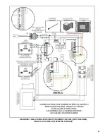
Страница 23: ...23 REQUIRES 2 RELAY SPNO SPNC WHITE ROGERS P N 90 380 NOT INCLUDED AND 24V AVAILABLE ON EXISTING FURNACE ...
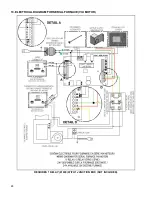
Страница 24: ...24 13 ELECTRICAL DIAGRAM FOR SERIAL FURNACE VIA MOTOR REQUIRES 1 RELAY 51035 WITH 1 JUNCTION BOX NOT INCLUDED ...
Страница 63: ...63 20 GENERAL ELECTRICAL DIAGRAM STANDALONE FURNACE ...
Страница 64: ...64 21 ELECTRICAL DIAGRAM FOR PARALLEL FURNACE ...
Страница 65: ...65 22 ELECTRICAL DIAGRAM FOR ELECTRIC UNIT ...
Страница 78: ...78 31 ELECTRICAL DIAGRAM BECKETT OIL UNIT ...
Страница 79: ...79 32 ELECTRICAL DIAGRAM RIELLO OIL UNIT ...
Страница 81: ...81 33 4 AIR CONDITIONNING DAMPER 33 5 HUMIDIFIER 33 6 HEAT PUMP ...
Страница 82: ...82 34 EXPLODED VIEW AND PART LIST ...
Страница 83: ...83 ...
Страница 84: ...84 ...
Страница 85: ...85 ...
Страница 86: ...86 ...
Страница 87: ...87 ...
Страница 88: ...88 ...
Страница 89: ...89 ...

