41
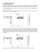
To ensure a safe installation, the two furnaces must not, at any time, run simultaneously. To do so, the thermostat
controlling the existing furnace must be connected to your Caddy link board. This way, when a heating signal is sent to
the existing furnace, the Caddy receives the same signal. It will tell the Caddy to either not start or, to go into a shut
down cycle, if the furnace was already heating when the demand for heat was sent.
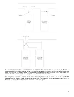
The wiring for an Add-on installation is shown below. The existing furnace’s thermostat must be connected to the
Rh
and
Aux
terminals of the link board on the Caddy furnace. Those two wires must come from the
R
and
W
terminals of
the existing furnace’s thermostat so the link board receives the heat signal.
Содержание PF01015
Страница 10: ...10 ADD ON WOOD ONLY WOOD ELECTRIC WOOD OIL ...
Страница 13: ...13 INSTALLATION AND OPERATION INSTRUCTIONS CADDY ADD ON SERIAL INSTALLATION PF01015 ...
Страница 16: ...16 Option 3 Option 4 ...
Страница 17: ...17 EXAMPLE 1 EXAMPLE 2 ...
Страница 23: ...23 REQUIRES 2 RELAY SPNO SPNC WHITE ROGERS P N 90 380 NOT INCLUDED AND 24V AVAILABLE ON EXISTING FURNACE ...
Страница 24: ...24 13 ELECTRICAL DIAGRAM FOR SERIAL FURNACE VIA MOTOR REQUIRES 1 RELAY 51035 WITH 1 JUNCTION BOX NOT INCLUDED ...
Страница 63: ...63 20 GENERAL ELECTRICAL DIAGRAM STANDALONE FURNACE ...
Страница 64: ...64 21 ELECTRICAL DIAGRAM FOR PARALLEL FURNACE ...
Страница 65: ...65 22 ELECTRICAL DIAGRAM FOR ELECTRIC UNIT ...
Страница 78: ...78 31 ELECTRICAL DIAGRAM BECKETT OIL UNIT ...
Страница 79: ...79 32 ELECTRICAL DIAGRAM RIELLO OIL UNIT ...
Страница 81: ...81 33 4 AIR CONDITIONNING DAMPER 33 5 HUMIDIFIER 33 6 HEAT PUMP ...
Страница 82: ...82 34 EXPLODED VIEW AND PART LIST ...
Страница 83: ...83 ...
Страница 84: ...84 ...
Страница 85: ...85 ...
Страница 86: ...86 ...
Страница 87: ...87 ...
Страница 88: ...88 ...
Страница 89: ...89 ...

