49
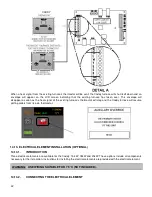
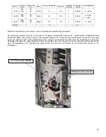
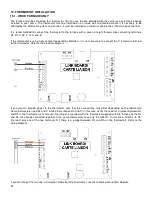
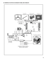
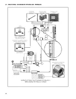
Mandatory thermostat connexions to connect a heat pump
Single stage thermostat:
Rh / Rc: No jumper required, already connected on the board
C: Common
Y: Activate the heat pump compressor
G: Activate the blower (In circulation mode)
O: Activate the reversing valve to cool
2
nd
stage connexion or Aux or E (when available)
W: Activate the electrical unit
16. CONFIGURATION AND OPERATING INSTRUCTIONS
16.1. CONTROLS SYSTEM
The Caddy has a sophisticated electronic control. This system is more versatile. All connections are made from the
control panel. Terminal blocks are provided for all components and options.
Before you configure your system and learn how to operate it, make sure that your wall thermostat is wired correctly to
your furnace, that the temperature probe (RTD) is well installed in the hot air plenum and connected to the link board
and that your air distribution system is complete.
The furnace uses a touch screen, the latest technology in control devices. Blowers and power supplies are controlled
from this screen.
It is important to note that your furnace is equipped with three main electronic components: the link board, the power
board and the touch screen. The power board is already installed on the furnace.
The power board is used to supply current to the different electrical components, in particular:
-
Supply current to the different electronic boards;
-
Supply current to the distribution fan;
-
Supply current to the sequencers of the electrical unit (optional);
-
Supply current to the oil burner.
The link board is used more precisely for:
-
Connecting the hot air plenum’s temperature probe (RTD type);
-
Connecting the wall thermostat;
-
Connecting complementary equipments;
-
Connecting a heat pump.
The LCD touch screen is used to operate the system. More precisely for:
-
Choosing the combustion parameters;
-
Selecting the options used;
-
Show the temperature in the hot air plenum;
-
Selecting heating priority;
-
Selecting language and units displayed;
-
Viewing statistics;
-
Selecting distribution fan speeds;
-
Troubleshooting to detect problems with the appliance.
16.2. SYSTEM CONFIGURATION
Once the installation is complete and before using the unit, the furnace should be configured to activate all applicable
functions depending on options chosen. To do this, it is important to know which options are installed on your furnace.
Содержание PF01015
Страница 10: ...10 ADD ON WOOD ONLY WOOD ELECTRIC WOOD OIL ...
Страница 13: ...13 INSTALLATION AND OPERATION INSTRUCTIONS CADDY ADD ON SERIAL INSTALLATION PF01015 ...
Страница 16: ...16 Option 3 Option 4 ...
Страница 17: ...17 EXAMPLE 1 EXAMPLE 2 ...
Страница 23: ...23 REQUIRES 2 RELAY SPNO SPNC WHITE ROGERS P N 90 380 NOT INCLUDED AND 24V AVAILABLE ON EXISTING FURNACE ...
Страница 24: ...24 13 ELECTRICAL DIAGRAM FOR SERIAL FURNACE VIA MOTOR REQUIRES 1 RELAY 51035 WITH 1 JUNCTION BOX NOT INCLUDED ...
Страница 63: ...63 20 GENERAL ELECTRICAL DIAGRAM STANDALONE FURNACE ...
Страница 64: ...64 21 ELECTRICAL DIAGRAM FOR PARALLEL FURNACE ...
Страница 65: ...65 22 ELECTRICAL DIAGRAM FOR ELECTRIC UNIT ...
Страница 78: ...78 31 ELECTRICAL DIAGRAM BECKETT OIL UNIT ...
Страница 79: ...79 32 ELECTRICAL DIAGRAM RIELLO OIL UNIT ...
Страница 81: ...81 33 4 AIR CONDITIONNING DAMPER 33 5 HUMIDIFIER 33 6 HEAT PUMP ...
Страница 82: ...82 34 EXPLODED VIEW AND PART LIST ...
Страница 83: ...83 ...
Страница 84: ...84 ...
Страница 85: ...85 ...
Страница 86: ...86 ...
Страница 87: ...87 ...
Страница 88: ...88 ...
Страница 89: ...89 ...

