80
33. LINK BOARD OPTIONS CONNECTIONS
33.1. ELECTRICAL CONSUMPTION
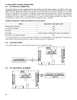
Your Caddy furnace is able to supply electrical 24V current to control various options. The options that can be
supported are described in the table below. The maximum available 24V current for the accessories is 1A The table
below shows the approximate electrical consumption of each of the options that can be installed with your Caddy
furnace. It is important to note that those consumptions were determined according to the maximum consumption of
the options tested by the manufacturer. It is possible to find on the market options having higher or lower electrical
consumption than those shown in the table below. In the event that the combined electrical consumption of the
installed options is higher than 1A, contact our technical support for further information.
WARNING: INCORRECT WIRING CAN DAMAGE THE LINK BOARD.
Option
Approximate consumption (mA)
Additional 24V equipment
500
Air conditioning damper
500
Humidifier
500
Heat pump
Current supply via additional transformer (not provided)
Thermostat (if not battery powered)
500
* It is important that the sum of the electrical consumption of the installed options is not higher than 1A. Note that the
water valve can draw more than 200 mA as long as the total current of 1A is respected.
33.2. OUTDOOR PROBE
* The outdoor probe act as a switch therefore it does not consume electrical current.
33.3. 24V ADDITIONNAL EQUIPMENT
Содержание PF01015
Страница 10: ...10 ADD ON WOOD ONLY WOOD ELECTRIC WOOD OIL ...
Страница 13: ...13 INSTALLATION AND OPERATION INSTRUCTIONS CADDY ADD ON SERIAL INSTALLATION PF01015 ...
Страница 16: ...16 Option 3 Option 4 ...
Страница 17: ...17 EXAMPLE 1 EXAMPLE 2 ...
Страница 23: ...23 REQUIRES 2 RELAY SPNO SPNC WHITE ROGERS P N 90 380 NOT INCLUDED AND 24V AVAILABLE ON EXISTING FURNACE ...
Страница 24: ...24 13 ELECTRICAL DIAGRAM FOR SERIAL FURNACE VIA MOTOR REQUIRES 1 RELAY 51035 WITH 1 JUNCTION BOX NOT INCLUDED ...
Страница 63: ...63 20 GENERAL ELECTRICAL DIAGRAM STANDALONE FURNACE ...
Страница 64: ...64 21 ELECTRICAL DIAGRAM FOR PARALLEL FURNACE ...
Страница 65: ...65 22 ELECTRICAL DIAGRAM FOR ELECTRIC UNIT ...
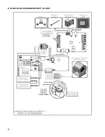
Страница 78: ...78 31 ELECTRICAL DIAGRAM BECKETT OIL UNIT ...
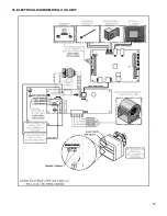
Страница 79: ...79 32 ELECTRICAL DIAGRAM RIELLO OIL UNIT ...
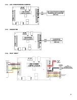
Страница 81: ...81 33 4 AIR CONDITIONNING DAMPER 33 5 HUMIDIFIER 33 6 HEAT PUMP ...
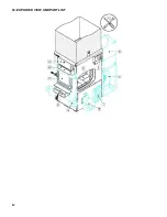
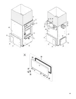
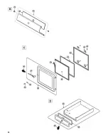
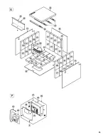
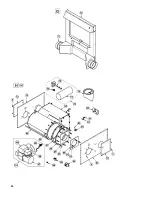
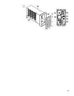
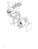
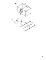
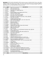
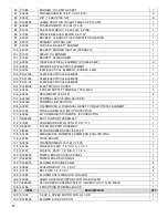
Страница 82: ...82 34 EXPLODED VIEW AND PART LIST ...
Страница 83: ...83 ...
Страница 84: ...84 ...
Страница 85: ...85 ...
Страница 86: ...86 ...
Страница 87: ...87 ...
Страница 88: ...88 ...
Страница 89: ...89 ...

