Synergy Technician's Software Reference Page 1
In addition to the
Maintenance Screen
, there is also a
Diagnostic Screen
and
Calibrate Screen
that are used
to manually operate specific components of the Synergy.
There are additional settings that may require fine-tuning
is a component fails and requires changing. Your software
version may be out of date with this manual. To confirm
the software version while the software is running press the
Synergy Logo
on the
Navigation bar
and the version will
appear. There may be other features in your system that
you do not find listed here. It is advised that these features
be ignored and treated as non-operational.
Calibrate Screen
When the
Calibrate Screen
is loaded, the technician
needs to press
Begin Calibration
to enable the calibration
sequences. This will prevent automated processes from
disrupting the calibration process. When the technician is
complete with Calibration, press
Stop Calibration
. The
technician will not be able to exit the
Calibration Screen
until they press
Stop Calibration
.
Every Calibration sequence will feature specific instruc
-
tions for the calibration. A
Finish Calibration
button or
Cancel Calibration
appears in the bottom right to exit
calibration before the end of the sequence. Some calibra-
tions are multi-step processes that will feature a
Next Step
button next to the
Finish/Cancel
button.
●
Test Valve Mappings
: Check if the Valves are
operating as intended by automatically cycling a
specific target valve every 5 seconds.
●
Calibrate Source Tanks
: Calibrate the scales for
the Source Tanks. It involves placing an empty
container on the scale and gradually filling it.
●
Calibrate Nozzles
: Carriages assembled at Brown
Manufacturing are tested for a target performance
standard. If it is suspected that the system is not
spraying correctly, use this sequence to confirm the
calibration. It is not advised to change the values
presented in this screen without a Brown Manufac-
turing Technician available.
●
Calibrate Projector
: This sequence calibrates the
size and placement of the load zone on the belt.
If the load zone had drifted or it is not displaying
correctly, go through these steps to correct any
miscalibration in the projector.
●
Calibrate Belts
: This sequence allows for calibrat
-
ing the lengths of each belt, as well as pretreater
settings relating to firefly operation.
Diagnostic Screen
The Diagnostic Screen allows for direct control of every
sub-component of the system, this includes all pumps,
valves, sensors, motors, control boards, and more. The
Diagnostic Screen features navigation buttons to quickly
jump to where a particular form of diagnostic begins. This
screen is most useful in diagnosing bad parts, and confirm
-
ing the operation of misbehaving parts. Page Navigation
can be used by pressing on the arrows at the bottom of the
screen.
●
Plumbing
: Jumps to the first page, where control
and feedback of plumbing begins.
●
Motors
: Jumps to the first page of motors diagnos
-
tic, where motors can be controlled directly.
●
Software
: Jumps to the first page of Software di
-
agnostic, where the software can be controlled and
monitored directly.
●
Last Page
: Jumps to the last page of diagnostics.
●
Stop All
: Stops all current plumbing and motor
operations. Uses a hard stop on every motor, and
resets all internal state machines.
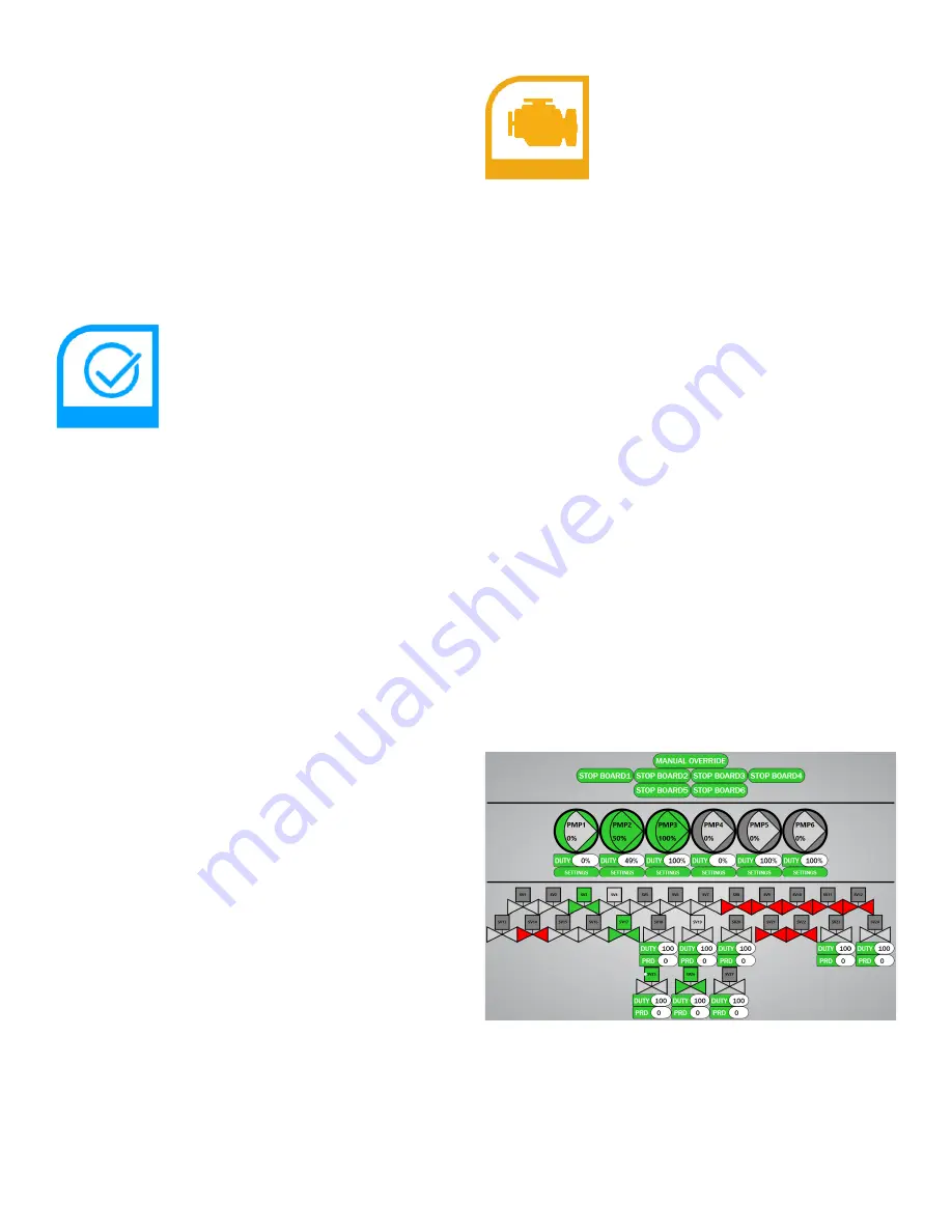
Plumbing Control
The plumbing control screen includes
Pumps
,
Valves
and
Boards
. There is also a
Manual Override
button which
temporarily disables mixing. The
Stop Board
buttons
disable the pump and valves associated with that board.
Image 1
Image 1: Plumbing Control Screen
The
Pumps
use the same symbol found in the
Plumbing
Schematic
and are labeled
PMPx
, with the inside of the
triangle representing feedback from the pump, and the
outside of the triangle representing control to the pump. If
the area is
gray
then the state has not changed since startup,
if the area is
white
then the state is currently inactive, if the


