


2. Reconnect the transceivers and cables to the port blades.
NOTE
The ports and cables used in trunking groups must meet specific requirements. For a list of these requirements, refer
to the
Brocade Fabric OS Administration Guide
.
a)
Position one of the transceivers so that the key is oriented correctly to the port and insert the transceiver into the port until it
is firmly seated and the latching mechanism clicks.
b) Select the cable that corresponds to the port and position it so that the key (the ridge on one side of the cable connector) is
aligned with the slot in the transceiver. Insert the cable into the transceiver until the latching mechanism clicks.
c)
Repeat step a and step b for the remaining ports.
d) Organize the cables as required.
NOTE
Do not route cables in front of the air exhaust vents.
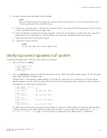
Verifying correct operation of system
Complete the following steps to verify the correct operation of the device.
1. Log in to the device as
admin
.
switch:admin> login
login: admin
password: xxxxxxxx
switch:admin>
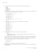
2. Enter the
chassisShow
command to verify that airflow direction set on WWN cards matches airflow direction for fans in fan and
power supply assemblies installed in device.
Airflow direction of fans and power supplies displays as "Fan Direction" under each fan or power supply unit. System airflow
direction displays as "System Airflow" under the WWN card unit. The following example shows mismatch of system airflow and
airflow direction in installed fan and power supply.
POWER SUPPLY Unit: 1
Power Source: AC
Fan Direction: Non-portside Intake
...
FAN Unit: 2
Fan Direction: Non-portside Intake
...
WWN Unit: 1
System AirFlow: Non-portside Exhaust
...
WWN Unit: 2
System AirFlow: Non-portside Exhaust
The WWN units should indicate "Non-portside Intake." If there is a mismatch of airflow direction, RASlog messages will indicate
a mismatch between system airflow direction and airflow direction of fan in power supply or fan assembly refer to
airflow direction on WWN cards
on page 177 for instructions on configuring correct airflow direction on WWN cards.
Verifying correct operation of system
Brocade X6-4 Director Hardware Installation Guide
53-1004106-07
221
Содержание X6-4
Страница 12: ...Brocade X6 4 Director Hardware Installation Guide 12 53 1004106 07...
Страница 20: ...Brocade X6 4 Director Hardware Installation Guide 20 53 1004106 07...
Страница 28: ...Brocade X6 4 Director Hardware Installation Guide 28 53 1004106 07...
Страница 64: ...Brocade X6 4 Director Hardware Installation Guide 64 53 1004106 07...
Страница 86: ...Brocade X6 4 Director Hardware Installation Guide 86 53 1004106 07...
Страница 102: ...Brocade X6 4 Director Hardware Installation Guide 102 53 1004106 07...
Страница 130: ...Brocade X6 4 Director Hardware Installation Guide 130 53 1004106 07...
Страница 140: ...Brocade X6 4 Director Hardware Installation Guide 140 53 1004106 07...
Страница 166: ...Brocade X6 4 Director Hardware Installation Guide 166 53 1004106 07...
Страница 196: ...Brocade X6 4 Director Hardware Installation Guide 196 53 1004106 07...
Страница 200: ...Brocade X6 4 Director Hardware Installation Guide 200 53 1004106 07...
Страница 204: ...Brocade X6 4 Director Hardware Installation Guide 204 53 1004106 07...
Страница 210: ...Brocade X6 4 Director Hardware Installation Guide 210 53 1004106 07...
Страница 224: ...Brocade X6 4 Director Hardware Installation Guide 224 53 1004106 07...
Страница 238: ...Brocade X6 4 Director Hardware Installation Guide 238 53 1004106 07...