Troubleshooting Guide
27
PROBLEM
DIAGNOSTIC CHECK
RESULT
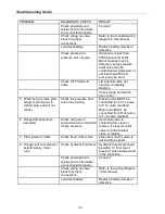
Check for voltage between
the other large terminal of
the solenoid and ground
while jumping power to the
small terminals with the
white wire.
If NO voltage is present,
solenoid has failed and
must be replaced. If voltage
is present, wire from small
terminal of solenoid to
ground may be
disconnected or broken.
Test power to the control
box by checking voltage
between black wire and
ground at the white 9-pin
connector.
If NO voltage is present,
power from relay has
become disconnected. If
voltage is present check
wiring and controller
switches.
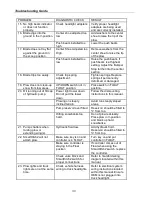
2. Pump continues to run
with switch in neutral.
Disconnect control box,
ignition ON.
If pump continues to run,
solenoid has failed in the
closed position. Quickly
remove power to the pump
by disconnecting the
power/ground cables to the
plow. Replace solenoid.
If pump stops running,
check wiring of controller
for short between black and
white/black wire in
controller, or failed switch.
3. Plow will not lower.
Check power/ground
cables and control cables
are connected properly.
Connect.
Check flow control valve.
If flow control valve is
completely closed, place
RAISE/LOWER switch in
NEUTRAL, then open the
flow control valve.
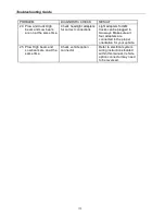
Check wiring on valve
block for proper
connections.
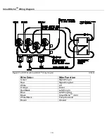
Refer to the wiring diagram
in this manual.
Check for voltage between
solenoid valve terminal
and ground with ignition
switch on and control
switch in FLOAT position.
If voltage is present
solenoid valve or valve coil
has failed. Replace valve.
Test power to the control
box by checking voltage
between black wire and
ground at the white 9-pin
connector.
If NO voltage is present,
power from relays has
become disconnected. If
voltage is present, check
wiring and switch of
controller.
4. Plow will not raise or
raises slowly (pump
motor runs).
Check hydraulic fluid level. Hydraulic fluid level should
be within ¾” from top of
reservoir when lowered and
in the V-position.
Содержание SMARTHITCH2 RT3 POWER-V
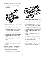
Страница 3: ...Snowplow Mounting Procedure 3 Figure 1 Mounting and Removal Instructions MSC04606 ...
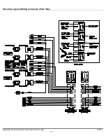
Страница 15: ...Electrical System Wiring Schematic Plow Side 15 Figure 24 Electrical System Wiring Schematic Plow Side G10271 ...
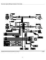
Страница 17: ...Electrical System Wiring Diagram 17 Figure 26 Electrical System Wiring Diagram G10134 ...


