Electrical System Wiring Procedure
9
Electrical System Wiring
Procedure
WARNING!
WARNING!
WARNING!
WARNING!
Before starting any Electrical Wiring Procedure
make sure that the engine is not running and that
the engine has had sufficient time to cool down.
Failure to do so may result in serious bodily injury
or death.
WARNING!
WARNING!
WARNING!
WARNING!
Before starting any Electrical Wiring Procedure
make sure to disconnect the battery. Failure to
do so may result in serious bodily injury or death.
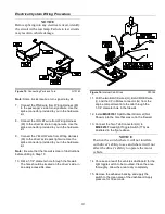
Figure 13.
Driver’s Side Headlight
G10140
Note:
Dielectric grease should be applied to all
electrical connections.
1. Disconnect the driver’s side headlight connector
plug (C) from the back of the driver’s side vehicle
headlight.
2. Connect the Blue Sealed Beam Connector (A)
from Wiring Harness (60) into the back of the
driver’s side vehicle headlight.
3. Connect the Black Rubber Connector (B) from
Wiring Harness (60) into the OEM Wiring Harness
(C). OEM Wiring Harness (C) is the vehicle
connector that was unplugged from the back of
the headlight in Step 1.
Note:
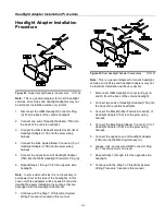
If your connectors do not match the connectors
on the wiring harness or you have a four-headlight
system a Headlight Adapter Kit will be needed. If you
are installing a Headlight Adapter Kit, See “Headlight
Adapter Installation Procedure” located in this manual.
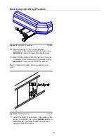
Figure 14.
Passenger’s Side Headlight
G10141
4. Disconnect the passenger’s side OEM Wiring
Harness (F) from the back of the passenger’s side
vehicle headlight.
5. Connect the Blue Sealed Beam Connector (D)
from Wiring Harness (60) into the back of the
passenger’s side vehicle headlight.
6. Connect the Black Rubber Connector (E) from
Wiring Harness (60) into the OEM Wiring Harness
(F). OEM Wiring Harness (F) is the vehicle
connector that was unplugged from the back of
the headlight in Step 4.
Содержание SMARTHITCH2 RT3 POWER-V
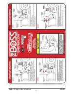
Страница 3: ...Snowplow Mounting Procedure 3 Figure 1 Mounting and Removal Instructions MSC04606 ...
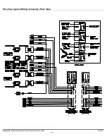
Страница 15: ...Electrical System Wiring Schematic Plow Side 15 Figure 24 Electrical System Wiring Schematic Plow Side G10271 ...
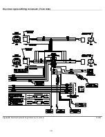
Страница 17: ...Electrical System Wiring Diagram 17 Figure 26 Electrical System Wiring Diagram G10134 ...


