Headlight Adapter Installation Procedure
14
Headlight Adapter Installation
Procedure
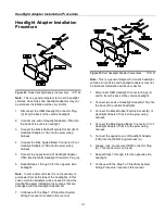
Figure 22.
Single
Headlight Adapter Connections
G10149
Note:
This is a general diagram for most 2-headlight
vehicles. All vehicles and headlight adapters may not
be identical. Installation will be very similar.
1. Disconnect the OEM Headlight Connector Plug
(A) from the back of the vehicle headlight.
2. Connect one end of Headlight Adapter (73A) into
the back of the vehicle headlight.
3. Connect the Black Rubber Female Socket (B) of
Headlight Adapter (73A) into the plow wiring
harness.
4. Connect the Blue Sealed Beam Connector (C) of
Headlight Adapter (73B) into the plow wiring
harness.
5. Connect the opposite end of Headlight Adapter
(73B) into the OEM Headlight Connector Plug (A).
6. Repeat Steps 1 through 5 for the opposite side
headlight.
Note:
In some older vehicles it is not necessary to
pull power from both sides of the headlights. In this
case only three adapters will be needed. Follow the
Headlight Adapter Installation Instructions that are
packaged with the Headlight Adapter Kit.
7. Continue with the Step 7 of “Electrical System
Wiring Procedure” located in this manual.
Figure 23.
Dual Headlight Adapter Connections
G10151
Note:
This is a general diagram for most 4-headlight
vehicles. All vehicles and headlight adapters may not
be identical. Installation will be very similar.
1. Disconnect OEM Headlight Connector Plugs (A
and D) from the back of the vehicle headlight.
2. Connect two ends of Headlight Adapter (73A) into
the back of the vehicle headlights.
3. Connect the Black Rubber Female Socket (B) of
Headlight Adapter (73A) into the plow wiring
harness.
4. Connect the Blue Sealed Beam Connector (C) of
Headlight Adapter (73B) into the plow wiring
harness.
5. Connect the opposite end of Headlight Adapter
(73B) into the OEM Wiring Harness (A).
6. Grease, tuck, and secure OEM Connector Plug
(D). This connector is not used.
7. Repeat Steps 1 through 6 for the opposite side
headlight.
8. Continue with the Step 7 of “Electrical System
Wiring Procedure” located in this manual.
Содержание SMARTHITCH2 RT3 POWER-V
Страница 3: ...Snowplow Mounting Procedure 3 Figure 1 Mounting and Removal Instructions MSC04606 ...
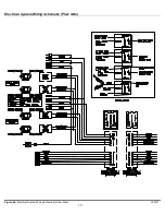
Страница 15: ...Electrical System Wiring Schematic Plow Side 15 Figure 24 Electrical System Wiring Schematic Plow Side G10271 ...
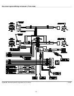
Страница 17: ...Electrical System Wiring Diagram 17 Figure 26 Electrical System Wiring Diagram G10134 ...


