RT3 Headlight Aiming Procedure
20
Headlight Aiming
Procedure
NOTICE
The installer of these snowplow lights must
certify that installation conforms to applicable
Federal Motor Vehicle Safety Standards.
1)
Place the vehicle on a level surface 25 feet in
front of a matte-white screen, such as a garage
door. The screen should be perpendicular to both
the ground and the vehicle.
2)
The vehicle should be equipped for normal
operation. The snowplow blade should be in place
and in the raised position.
3)
Below are some points listed by the Society of
Automotive engineers (SAE) pertinent to headlight
aiming. These points can be found in publication
#SAEJ5991D.
Preparation for Headlight Aim or Inspection
Before checking beam aim, the inspector shall:
•
Remove ice or mud from under fenders.
•
See that no tire is noticeably deflated.
•
Check vehicle springs for sag or broken
leaves.
•
See that there is no load in the vehicle other
than the driver.
•
Check functioning of any “level-ride” controls.
•
Clean lenses and aiming pads.
•
Check for bulb burnout, broken mechanical
aiming pads, and proper beam switching.
•
Stabilize suspension by rocking vehicle
sideways.
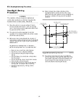
4)
Mark (or tape) the vehicle centerline of the
headlights and the vehicle itself on the screen.
Mark the horizontal centerline of the headlights on
the screen (distance from ground to headlight
centers).
Figure 29.
Headlight Aiming Procedure
G10153
5)
The correct visual aim for Type 2 headlights is
with the top edge of the high intensity zone of the
lower beam below the horizontal centerline and
the left edge of the high intensity zone on the
vertical centerline. See diagram above.
25' From Headlights
Screen Located
Align With Vehicle
Centerline
of Right Headlight
Vertical Centerline Ahead
High Intensity Zones
For Type 2 (Sealed Beam)
Headlights on Low Beam
Headlight Centers
Distance Between
Содержание SMARTHITCH2 RT3 POWER-V
Страница 3: ...Snowplow Mounting Procedure 3 Figure 1 Mounting and Removal Instructions MSC04606 ...
Страница 15: ...Electrical System Wiring Schematic Plow Side 15 Figure 24 Electrical System Wiring Schematic Plow Side G10271 ...
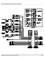
Страница 17: ...Electrical System Wiring Diagram 17 Figure 26 Electrical System Wiring Diagram G10134 ...


