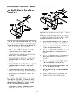
Snowplow Assembly Procedure
4
Snowplow Assembly
Procedure
Note:
This manual is used for the installation of all V-
Plows. Part numbers and illustrations may vary.
1. Begin the assembly procedure by cutting down
each corner of the plow box so that each wall of
the box will lie flat on the floor. Lay the top of the
box flat on the floor. The top of the box can be
used as a mat and will help prevent scratching the
blade halves during installation.
2. Remove Left Blade Half (5) and Right Blade Half
(4) from the crate. Lay each blade half flat on the
box top, face down.
Figure 2.
Blade Assembly Procedure.
G10123
3. Align the center bushings on Left Blade Half (5)
with the center bushings on Right Blade Half (4).
Position
CHA09716
Center Section (2) on top of
both blades so that all bushings align.
4. Insert
MSC01507
Center Hinge Pin (15) through
Left Blade Half (5), Right Blade Half (4) and
Center Section (2).
5. Secure Center Hinge Pin (15) to the top of Center
Section (2) using one
HDW01771
3/8”-16 X 1 ¼”
Hex Head Cap Screw (93), and one
HDW01718
3/8” Split Lock Washer (108).
Note:
Plow shoes are optional. If added they should
be mounted flush with the bottom of the cutting edge
when the plow is mounted on the truck to be used for
plowing. When plowing on a solid level area (parking
lots, roads, and driveways) plow shoes can be raised
up to increase cutting edge contact on the plowed
surface. When plowing dirt, gravel, or grass plow
shoes should be lowered below the cutting edge
surface to prevent the plow from digging into the
plowed surface.
Содержание SMARTHITCH2 RT3 POWER-V
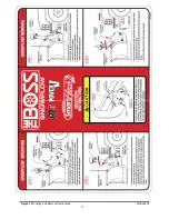
Страница 3: ...Snowplow Mounting Procedure 3 Figure 1 Mounting and Removal Instructions MSC04606 ...
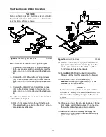
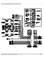
Страница 15: ...Electrical System Wiring Schematic Plow Side 15 Figure 24 Electrical System Wiring Schematic Plow Side G10271 ...
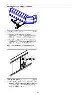
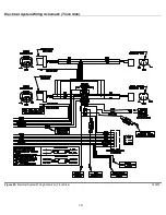
Страница 17: ...Electrical System Wiring Diagram 17 Figure 26 Electrical System Wiring Diagram G10134 ...


