Electrical System Wiring Procedure
11
16. Secure the 9 Pin Molex Connector (G) and wire
loom underneath the dashboard.
17. Plug the controller into the 9 Pin Molex Connector
(G).
18. Mount the plow control in a location that is
comfortable for the operator to reach, and where
the operator will not contact the control in the
event of a crash. (See “V-Blade Controller
Mounting Instructions” located in this manual.)
19. Connect the BLACK/RED wire (I) to a “keyed”
12V+ ignition source.
Note:
This 12V+ source should only be active when
the key is in the ON position. Failure to wire to a
“keyed” source can allow a condition to occur causing
the battery to drain.
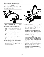
Figure 17.
Solenoid Connections.
G10145
20. Connect the WHITE/BLACK wire (J) of Wiring
Harness (60) to the small terminal on Pump
Solenoid (64).
21. Connect the BROWN wire (K) of Wiring Harness
(60) to the small terminal on Pump Solenoid (64).
Note:
Location of the wires on the small terminals
does not matter.
22. Attach Power Unit Solenoid (64) securely inside
the engine compartment. The Power Unit
Solenoid should be mounted in the upright
position as illustrated above.
Note:
The solenoid must be installed so that the
solenoid posts do not contact the body, hood, or any
other conductive material on the vehicle
.
23. Attach the eyelet end of RED Power/Ground
Cable (62) to the top of Pump Solenoid (64).
24. Connect Battery Cable (66) to the top post of
Pump Solenoid (64).
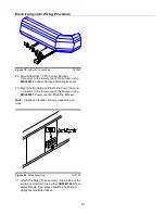
Figure 18.
Battery Connections
G10146
25. Attach the eyelet end (N) of BLACK
Power/Ground Cable (62) to the negative battery
terminal.
26. Connect the BROWN wire (Q) to the negative
battery terminal.
27. Connect the unattached end (P) of Battery Cable
(66) to the positive battery terminal.
28. Connect the RED Fused wire (O) to the positive
battery terminal.
NOTICE
Be sure the wire loom does not interfere with the
operation of the vehicle’s pedals.
Содержание SMARTHITCH2 RT3 POWER-V
Страница 3: ...Snowplow Mounting Procedure 3 Figure 1 Mounting and Removal Instructions MSC04606 ...
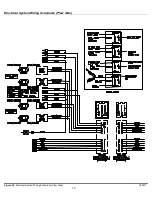
Страница 15: ...Electrical System Wiring Schematic Plow Side 15 Figure 24 Electrical System Wiring Schematic Plow Side G10271 ...
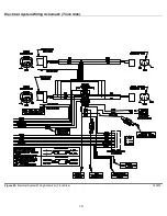
Страница 17: ...Electrical System Wiring Diagram 17 Figure 26 Electrical System Wiring Diagram G10134 ...


